Optimizing Processes with Engineering Fundamentals

Hi Everyone,

Given the vast permutations of processes that exist so far in this industry and the relative infancy of our empirical understanding of them, I feel like an engineering perspective could really cut through the fat and allow individuals to make more effective and appropriate decisions when it comes to making process decisions.

For example, I want to buy a condenser for solvent recovery. I want the unit to be able to recover 100 gallons / hour of ethanol (or hexane, or whatever)…what steps do I take to ensure I’m procuring the best possible unit for my operation? What preliminary calculations can I make to narrow my choices? How can I alter some operating constraints to optimize my use of electricity and cooling water (in this case)?

Welp, i’m a chemical engineer in a non-legal state, so the only way I can contribute is by sharing my engineering knowledge in any way I can. I’m not a consultant, I don’t expect any compensation, I just want to expand my knowledge and apply it in a useful way.

All that being said, does anyone have any questions about how to optimize their process?

Also, I work in validation if anyone has questions about SOP design and GMP. :slight_smile:

24 Likes

If I have 10c well water flowing at 10lpm, how much surface area do I need to condense 378lpm of ethanol vapor?

2 Likes

There are several details here that can drastically alter the calculations. First, we can either assume that the ethanol vapor entering the condenser is at its boiling point or needs to be cooled to its boiling point before it can condense. Next, will we be running at atmospheric pressure or at vacuum.

I have taken the liberty of assuming that the condenser duty is calculated for condensing ethanol at its boiling point and at atmospheric pressure. This simplifies things.

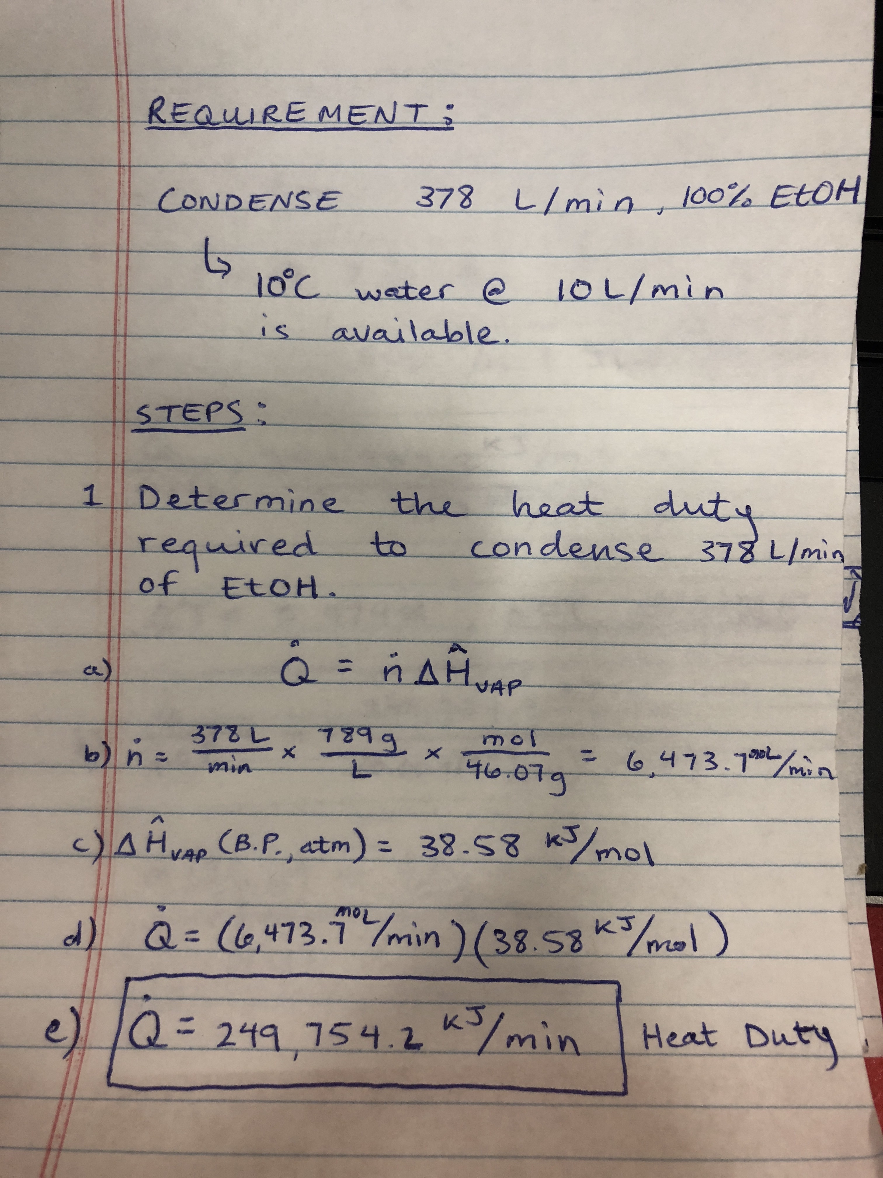
Now, calculate the heat required to condense the gaseous ethanol:

Qdot = ndot*Hvap

Qdot = Heat Duty Required
ndot = Molar Flow Rate of Gaseous Ethanol
Hvap = Specific Molar Heat of Vaporization for Ethanol

Molar flow rate is simply converting lpm to mole/min using density and molecular weight (i will provide my written calculations)

This gives ~ 250,000 kJ/min of Required Heat Duty JUST FOR CONDENSATION, NO COOLING.

Now, things begin to get extremely convoluted, complicated and open to design optimization.

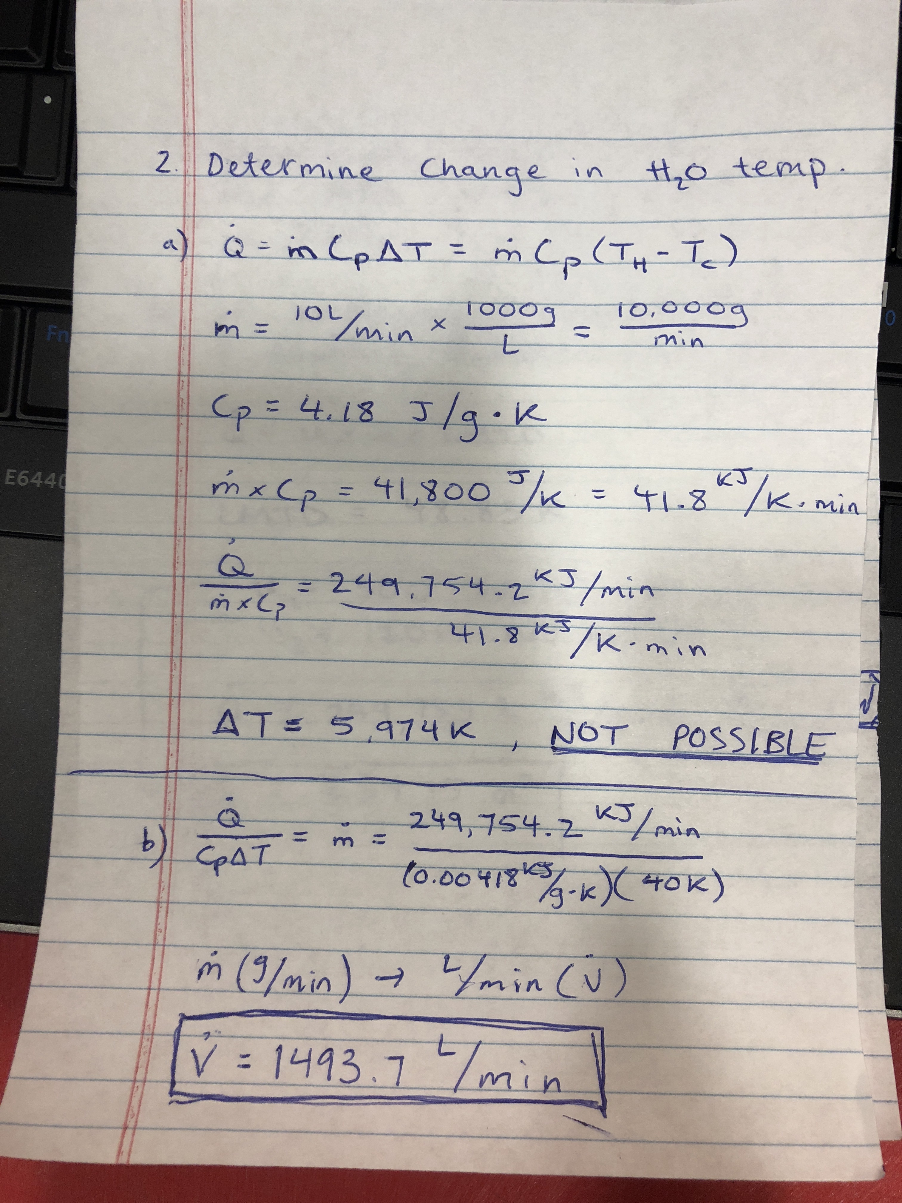
The first thing we want to do is see what kind of temperature change we would see for 10 lpm of water encountering this heat duty.

Qdot = mdotCp(Th-Tc)

Qdot = Same as above.
mdot = mass flow rate of water per minute
Cool = Heat capacity of water in (kJ/g*C)
Th, Tc = Temperature (in Celsius) of water exiting condenser and water entering condenser respectively.

For a 10 lpm Stream of water, the change in temperature is over 5000C! So clearly, we need to explore a different avenue.

Fortunately, there is an alternative way forward:
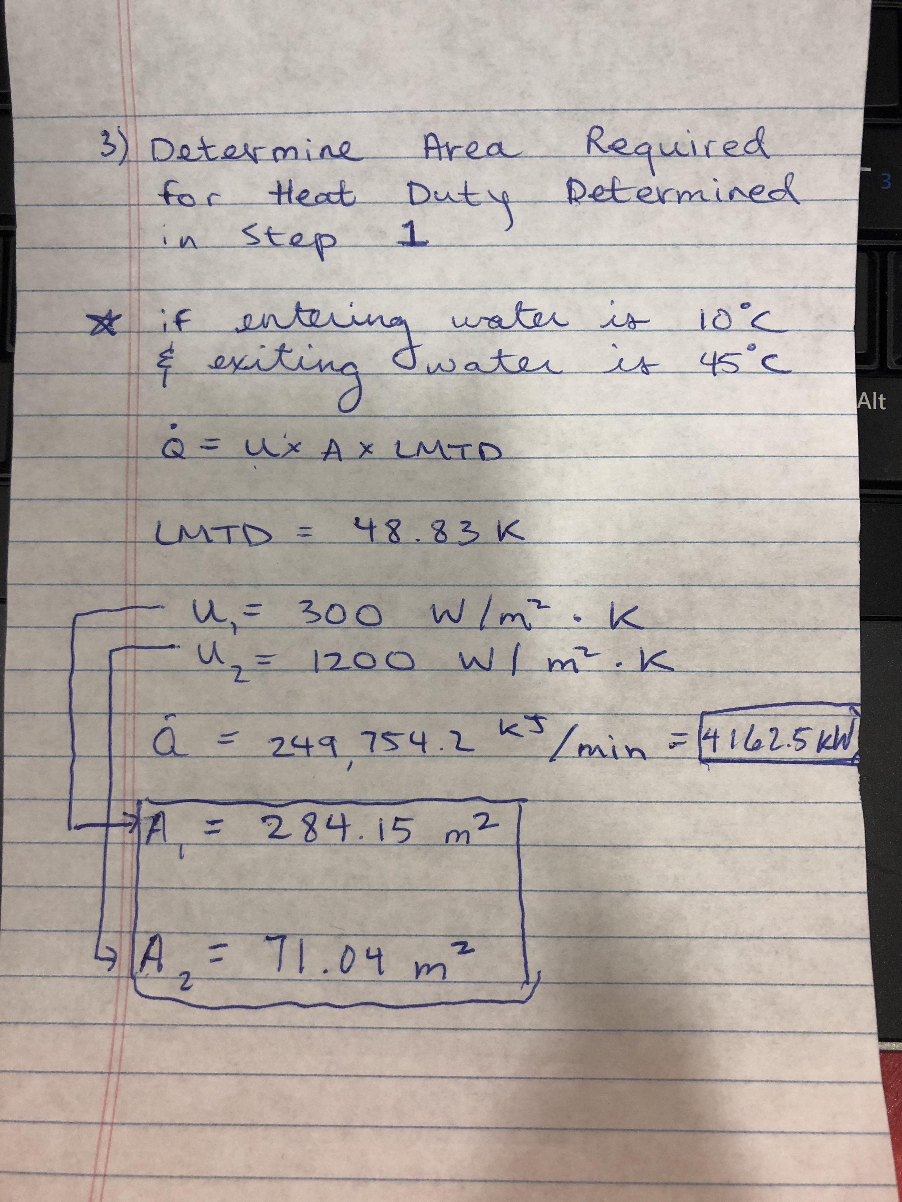
Qdot = UALMTD

U = Overall Heat Transfer Coefficient
A = Area available for Heat Transfer
LMTD = Log Mean Temperature Difference

Hoo boy, it just got even more complicated…
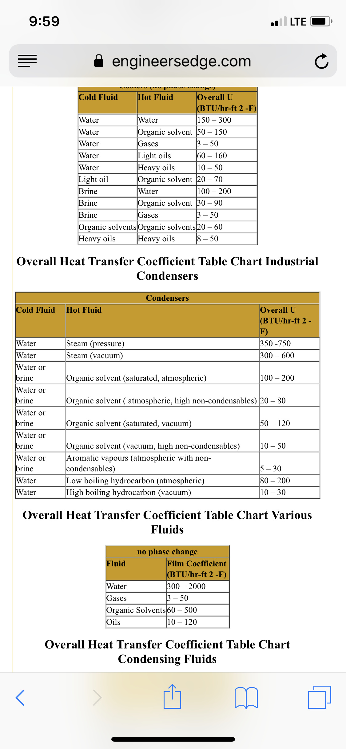
U is a difficult to calculate number that has ruined the life of many chemical engineers, but there are relatively decent approximations for given situations, in this case to condense an “organic solvent” with a cooling water stream can be found in the table below. So we will assume the extreme values and end up with a range of surface areas.

LMTD is essentially the difference between the difference of the cold stream and gaseous ethanol and the hot stream and gaseous ethanol, google it if you’re interested. BUT THIS MEANS I will have to assume the exit temperature of the cooling water—let’s say it’s 45 Celsius.

So now A = Qdot/(U*LMTD)

For the worst-case scenario A1 = 284.15 meters squared

A2 = 71.04 meters squared

Both insanely large areas, but 378 L/min is equivalent to nearly 430,000 kg/day of ethanol!!

Using all this data we can back calculate to see the required flow rate of water to cool this flow rate of ethanol using the second provided equation.

Anyways, anything confusing that I can clarify on, here?


20 Likes

Just as a heads up, one can accurately determine the surface area by determining U more accurately. This involves understanding of the Heat Transfer Equipment used, correction factors, laminar or turbulent flow, fouling, etc.

Also, I didn’t clarify but these surface areas are not reflective of a 10 lpm flow rate of cooling water. This number is much too. The minimum flow rate for an exit cooling water temp of 50 degrees is about 1700 lpm as seen above.

2 Likes

:slight_smile: I 2 r grateful Phil.

I was trying to invoke that exact maths for someone earlier in the day.

Told her she should go look it up (it’s for a masters level chem class…). Glad I can now try and wrap my head around it and perhaps be ready to check her work.

1 Like

You are an animal! And what if this is all happening at let’s say 100 micron of vacuum?

1 Like

Don’t want to get anything too wrong here, so a preliminary follow up question: when I try and find the boiling point of ethanol at 100 uHg (micron) it is around -63 Celsius.

Can you confirm or deny this? If so, do you have any data to confirm the BP of pure ethanol at this vacuum pressure

1 Like

You said pure alcohol, it may be likely that this evaporator will see a mix of slightly diluted etoh and resin. I know we are talking about condenser surfaces here, but what about the heat input side? What is the effect of having more or less resin in your input feed. How does this effect surface area of the feed stock boiler?

1 Like

I have a question. First thank you for offering advice. Very kind. I pushed your :heart: and will rub my Italian Grayhounds bellies in thanks. Awww.

I recently took under an ounce of crude concentrate testing 60% nominal THC and dissolved it in 100 ml hexane and transferred to my 500 ml sep funnel. The goal was to refine in preparation for further refinement later in a molecular short path recovery technique using a sublimation apparatus I employ.

I then started adding a methanol/water mix 100 ml at a time as a gradient. So the first 100 ml added was 90% water/10% methanol. After the layers seperated I drained the bottom layer of water and methanol. Then I repeated but at 10% higher concentration of methanol.

I began seeing color seperate out at about 60% methanol to 40% water. Somewhere up at 95% methanol to 5% water is where the cannabinoid seemed to come out the bottom layer with the water methanol mix. I had started reducing the jump in methanol to a few percent at a time. Left behind in the hexane was the darker tar like components. I have only done a few runs so this is as much data as I have.

How would you go about optimizing the process I described to selectively target cannabinoid or how could I better improve upon the idea?

2 Likes

Let me address the simplest issue first. Resin, it can be intuitively determined, has a much higher boiling point than EtOH. As B.P. is increased for a feedstock, the surface area required to deliver a heat-flux necessary for maintaining a specific rate of evaporation also increase. So as the %EtOH decreases and %Resin increases, expect an increase in boiler size to maintain the same effective rate of evaporation at the same temperature.

Now, boiling regimes become super difficult to quanitfy but as a preliminary investigation, the equation provided by P.J. Berenson in “Film-Boiling Heat Transfer From a Horizontal Surface” (1960) can be seen in the image below:

Which is to say, there is an immense amount of work that needs to be put in to calculation to determine an accurate relationship between ethanol concentration and boiling rate that probably exceeds the scope of our discussion here.

Now, if we focus our attention on a specific type of evaporator (wfe, ffe, rfe, batch distillation unit, etc) we can begin to hone in the theoretical calculations and get a narrower range for how a resin/EtOH mixture would behave.

3 Likes

Specifically falling film. I’ll have to get a couple more vac gauge hooked up, and ill give you my full data sets. This would probably be much easier if you knew all my known variables… I have found the unit evaporates significantly more etoh over a given time if it’s saturated with a super sticky resin

3 Likes

Super cool idea you have there and I dig the patience that went into your process. LLE, it seems to me, is an under-refined process relative to A lot of other chemical processes, but I have a cool idea to bounce off of you:

Set up two reaction vessels. In the first vessel, let’s call it A, mix hexane and crude until you are sure it’s homogenous. Then, mix in a certain amount of water (this will take some experimentation). Put a stir bar in and set at desired RPM.

Now the setup of this will begin to get a little weird…add MeOH dropwise to A and siphon out the reaction mixture slowly into reaction vessel B. Place B in as cold an environment as possible to speed up the separation of the immiscible fluids, then drain the water/MeOH mixture, which will become more concentrated in MeOH as more is added drop-wise to A.

If I have a second I will draw up a preliminary design for this idea, but I suspect that if you can manage to keep the level of liquid consistent throughout the process you will begin to find closer to exact percentages where your molecules of interest begin to drop out of hexane into your more polar solvents.

What do you think?

5 Likes

The more known variables definitely the more detail and accuracy I can provide.

1 Like

Anything to do with free energy?

1 Like

Elaborate…

What about free energy do you want to know more about?

2 Likes

Thank you sir, very informative! Ffe are getting popular these days, let’s optimize calculations around them. Thanks for the great reply!

1 Like

Are you sugggesting siphoning the bottom layer as methanol is added to maintain a constant level in the spinning mix in vessel A in the above quote? I am trying to visualize. :eyeglasses:

1 Like

No, I meant something like this, which would be solely to determine at what concentrations of MeO/Water your desired product ‘drops’ into the polar phase.

Once this information is determined, you can scale your process parameters to create something like a A KARR Column
image

2 Likes

Imagine that with a very slow dropwise Addition, vessel B will be adequately undisturbed and with the addition of an ice bath, one can assume that the immiscible liquids are separated to where only MeOH and water are removed. Moreover, you can calculate the concentration of each species in the well mixed vessel A as a function of addition of MeOH and removal of mixture.

I’m quite busy today but if you’re interested I can try to calculate the change in concentration for
A given rate of MeOH addition and mixture removal from A.

3 Likes

I need to stick with just a sep funnel really. Your idea is great but when it starts to get complex in apparatus I start to lose interest. I have to keep it simple :stuck_out_tongue_winking_eye:

I employ other means for isolating the target compound and the funnel sep was an experiment. My other methods are very efficient. The obvious attraction to a liquid sep if it worked well was no fiddling with silicon gel or any solid stationary phase at all… The reality is I will likely just run DCVC seps only as a prep after dewaxing. It just seemed more fussy to work with the sep funnel as described and was wondering if the solvent system could be tuned better than described.

I have previously transferred from the top of test tube to test tube as well but from the top hexane layer. A series of 12-15 tubes or so and an increasing stationary phase gradient in the tubes of methanol to water as the top is transferred along the chain of tubes was used. It pretty much nailed down for me what gradient to use in the sep funnel and more or less provided the same information of your well thought out device.

That process of course was tedious in the transfers of the hexane mobile phase and the gradient of the tubes changing.

Thanks for the interesting idea! I based my explorations on the topic on the paper in this link.