Howdy out there,
I am a relatively new extractor operating in the CA market and I’m frustrated beyond all hell with the lack of open source collaborative development in the space. To give a bit of background let me begin by saying that most of my experience has been within a corporate framework. I was the director of engineering at a mid sized (500 employee) manufacturing company for the better part of the last decade, and throughout my time there I found that the most successful projects ( at least in terms of innovative and novel designs) were those with the most collaborators and those with the most diverse pool of collaborators.
The extraction community is by far one of the most diverse groups I’ve ever been a part of and I suspect that if organized properly, open source design projects could leverage the decentralized collective knowledge base to create innovative and efficient designs that move the industry forward as a whole. I firmly believe that the people who will survive in this industry will be those who are able to focus on their core competency while developing relationships with other operators whose core competencies are in line with but not entirely overlapping their own. For instance, I focus on wholesale distillate because I am an engineer and a manufacturer with no experience in the retail and branding side, so I seek to align myself with companies that have these aspects covered but are in need of some help on the back end. I can’t logically dedicate my time to tasks that will require me to learn a new skillset or I am just wasting valuable time.
That being said - I have really been itching to design and build a dual effect falling film evaporator for bulk ethanol recovery and I believe it is the perfect project to open up to the community. At this point I have started to do rough calculations regarding the energy and heat transfer requirements to facilitate the evaporation and condensation of 20 gallons of ethanol in 1 to 1.5 hours.
The first task is definitely going to be a comprehensive list of target performance specs for the system and we will work backwards from there.
Before I dump more of my time and energy into the project, I want to gauge the level of interest and ask the extraction community what they are willing and able to contribute in terms of the design.
Here is what I plan to contribute:
-CAD modeling of system using SolidWorks
-Full set of technical drawings, including assembly drawings and BOM with supplier PNs if standard parts
-Optimization of design through CAD simulation of thermodynamic system
-Development, prototyping and testing of many types of custom parts (CNCs, Mills etc. at my disposal)
-Organization/delegation of tasks and general project management
Again, I really believe that all of us is better than any one of us and I’m stoked to see what we can make happen. I’ve put together a collaborative dropbox folder that currently contains some scholarly articles pertaining to analogous FFE systems for review. Feel free to send me anything you think is relevant to the project and I can add it to the dropbox for now until I can grant write access to contributing parties.
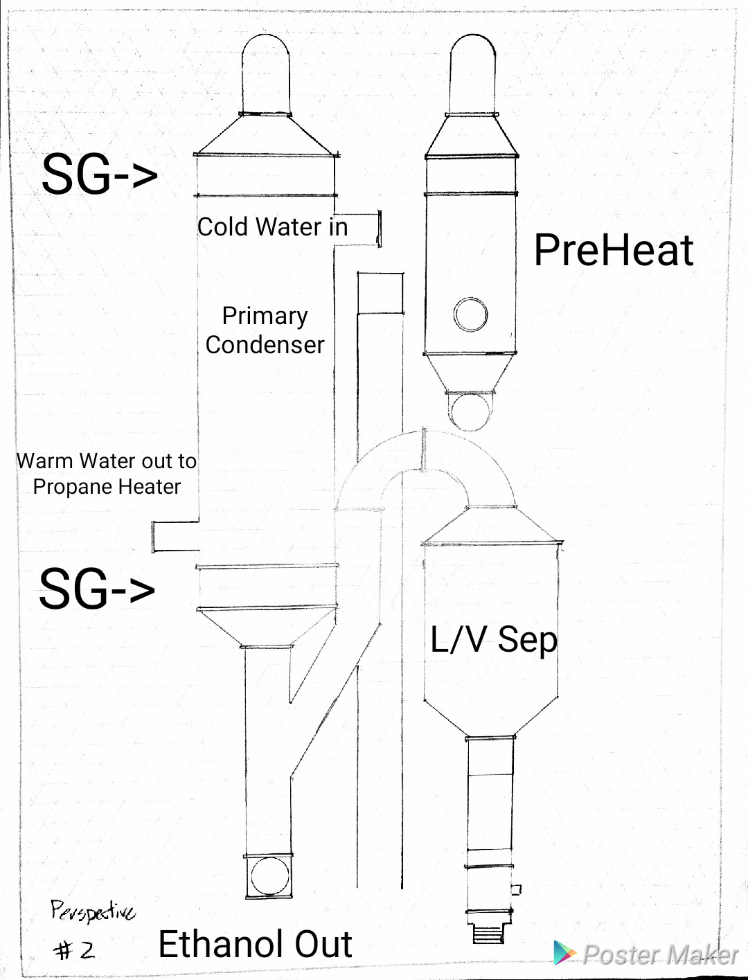
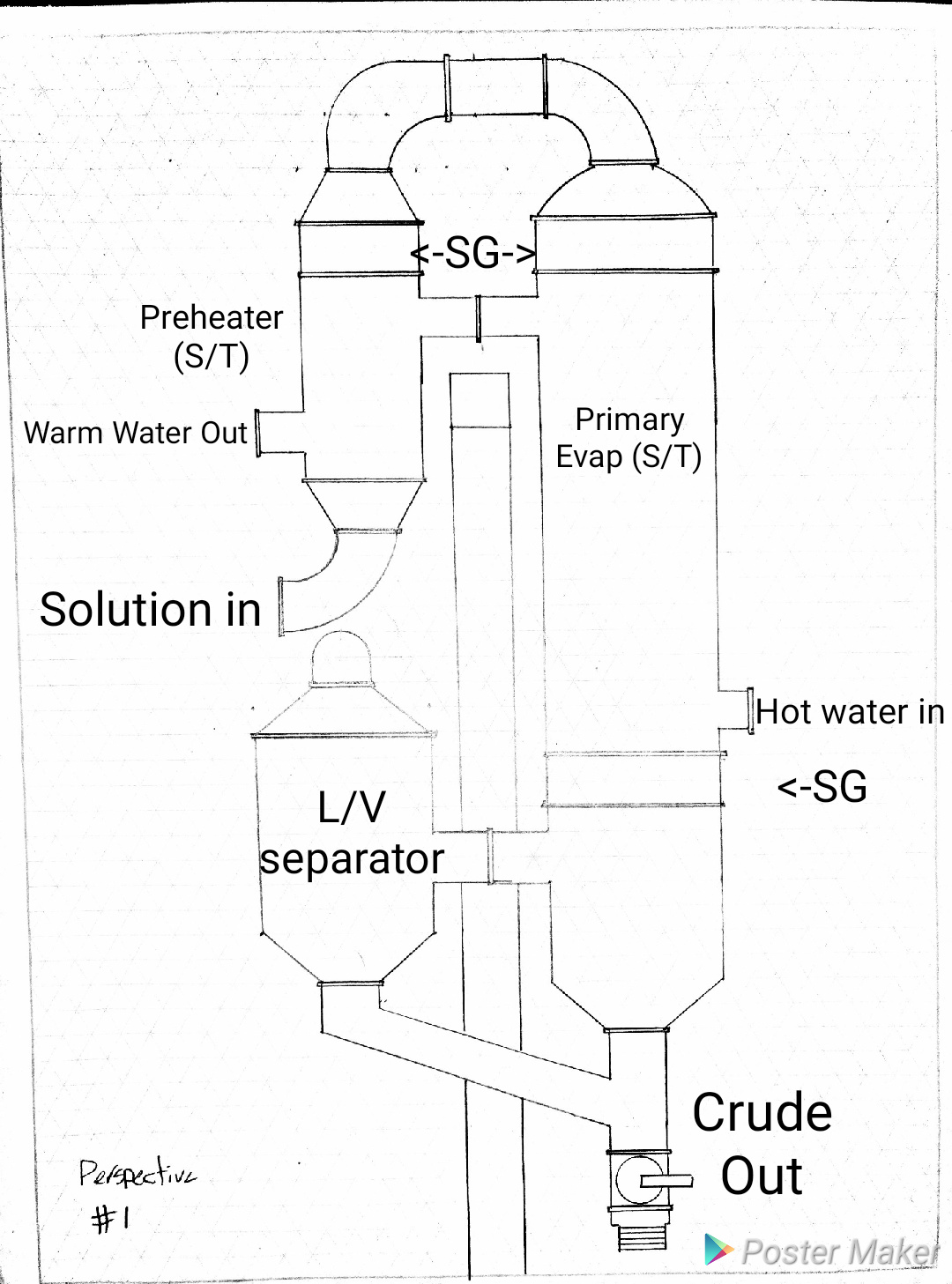
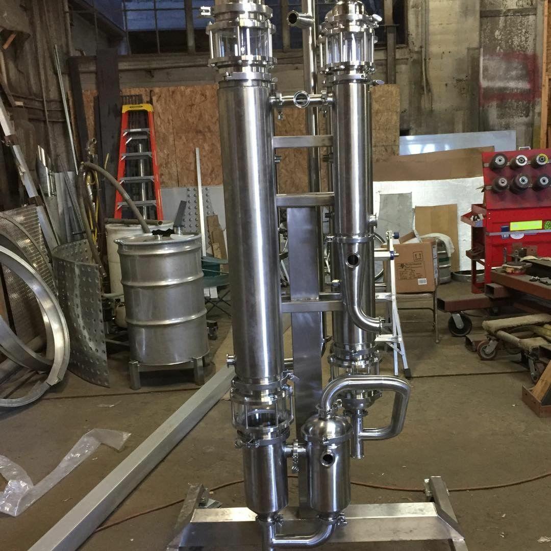
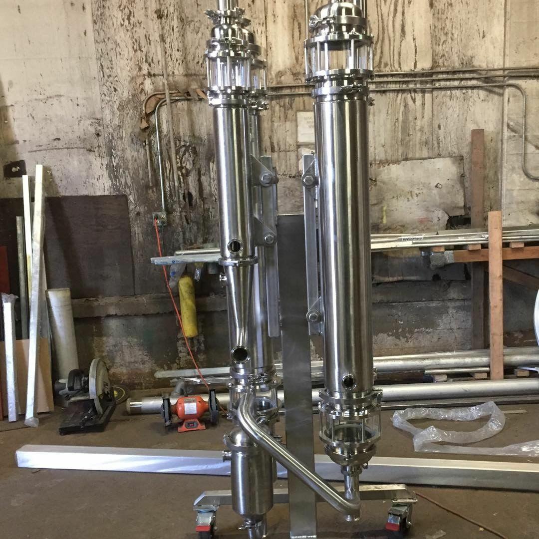
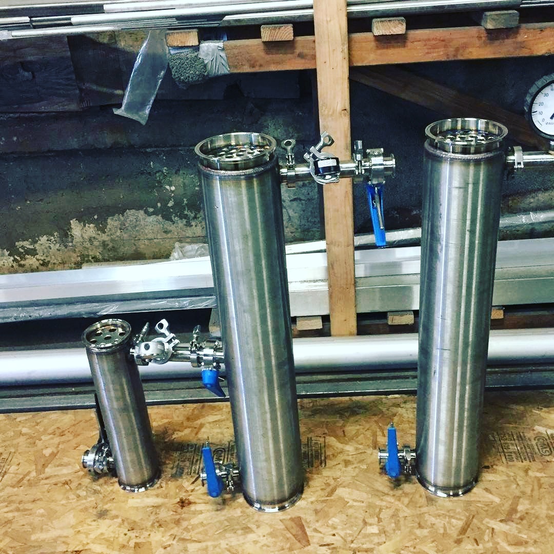
I couldn’t afford a @PinnacleStainless rising film when I needed that solution, so I designed my own and had AgileStainless build it for me.
We are on version 3, so I will gladly share my initial designs which we built the prototype around.
Keep in mind I am not an engineer, I just applied prior art and common sense to the design. The prototype runs 1gpm on well water for cooling, recycled through an 190k BTU propane fired instant hot water heater.
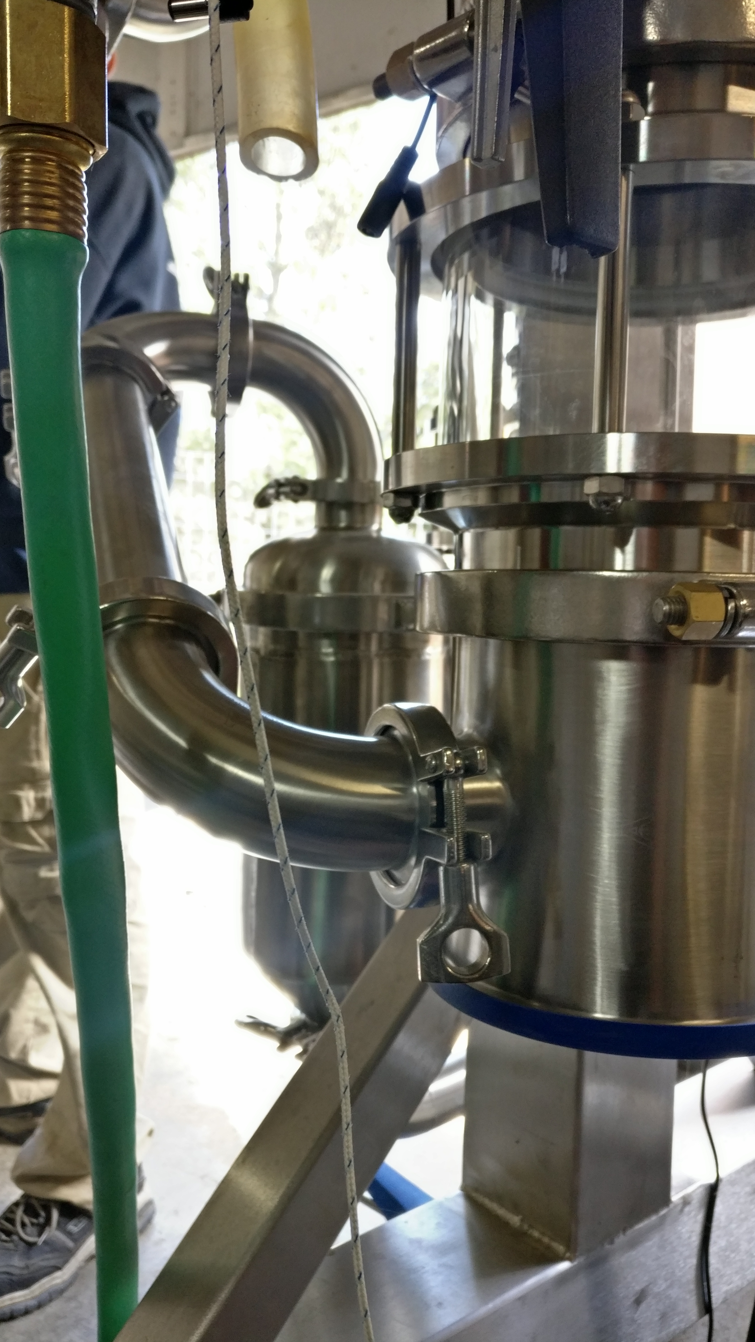
From the primary condenser I have a secondary condenser, both Shell and Tube. SG = Sight Glass. I’ll have to go back and look at the surface area, # of tubes, height, etc. One thing to note, choking down the pipe size so quickly beneath the primary condenser was a major design flaw
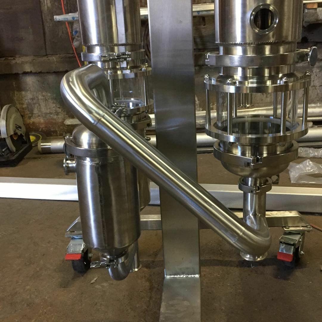
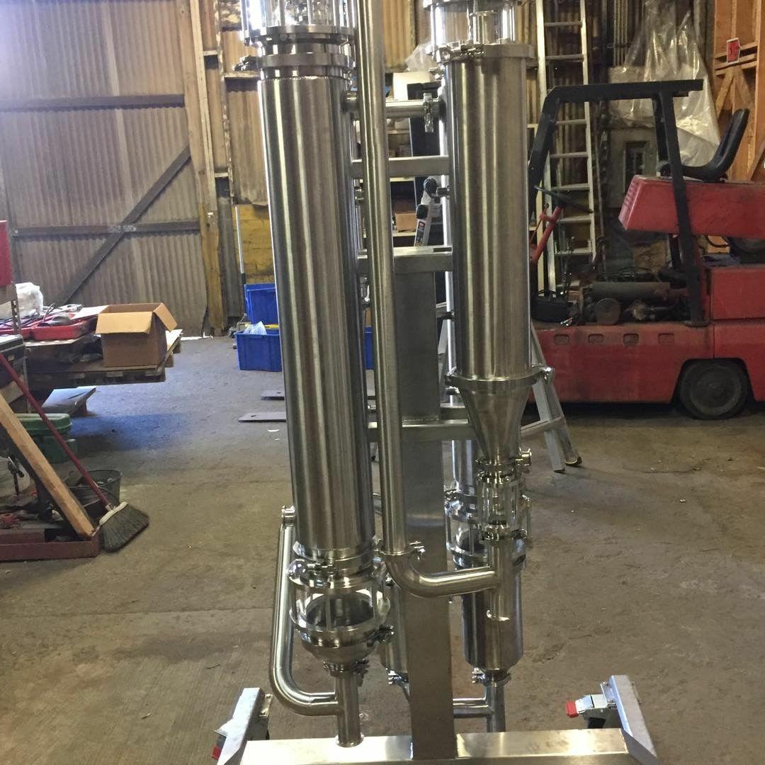
@Future Masterfully repurposed artwork! Thanks for providing this, it’s a great starting point. Would you be willing to give us a ballpark on your build cost? Were the heat exchangers and sanitary tube standard parts off the shelf? I imagine your stainless guy built the rack to mount everything but did you need custom parts as well?
Great idea. Sounds like we’re taking a similar path in this industry.
I’m a mechanical engineer currently working on a much larger scale design, as nothing on the market currently has the capacity I need. My target throughput is about an order of magnitude higher than we’re talking about here, but the principles are the same.
I would suggest looking at the BZB design, as it is clever, very effective, and he is very open about the design details on instagram and in other spots. That’s what I’ve been basing my design on. I would imagine that a scale-down rather than a scale-up would be easy enough to do with off-the shelf parts for the most part.
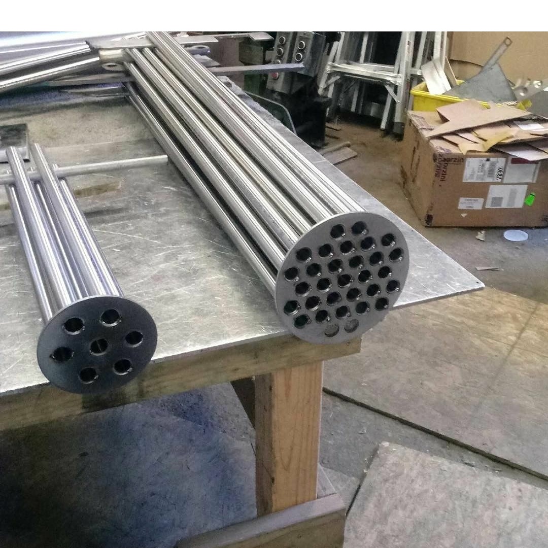
Future’s design above also looks very good to my eyes. Changes I would recommend to start with: keep all connecting piping at very close to the diameter of the heat exchangers where possible, and a much higher number of smaller tubes in the exchangers.
Either the BZB or the Future design or some combination of both would probably work very well. The fundamentals of evaporation/condensation are relatively simple. Of course, the devil is in the details.
I’ve got some excel sheets I put together for calculating energy requirements for my evaporator that I could clean up and modify for public consumption and provide to the community. My workload doesn’t allow me to commit much more right now, but if I can chip in with useful things here and there I will.
I’ve found it’s not really important for the piping size to match the evaporator (6" in this case) since the majority of the output is ethanol vapor. Also, the input side of the evaporator should definitely not be there same size as the evaporator. However, the output of the condenser it is crucial for the piping to be the same size as the condenser until the condensing ethanol has passed the incoming ethanol vapor.
Ah I should have clarified, the piping size comment comes primarily from a parts count / simplicity of manufacture standpoint. If this is to be an open source/diy-ish design keeping the smallest number of parts possible on the BOM is preferable, especially if we can keep them off the shelf.
@Lincoln20XX I really appreciate the input. I have been following BZB closely trying to get as much pertinent information as possible from what he makes available publicly - which is pretty much just the layout.
As far as throughput, I think that making the system modular with the intention of daisy chaining multiple dual effects to facilitate greater capacity. Im in a position to expand our extraction capability rapidly, but I dont want to put the cart before the horse, and I’d just be frustrating myself making tons of crude and having it pile up behind the Roto’s. I would be very interested in collaborating on a large scale FFE, but I figured that I would get more interest here from people who are just beginning to outgrow their rotory evaps. I’m also a firm believer in starting small, optimizing and developing the process until you are convinced you know what you are doing, then scaling it up. As the owner/operator, I try to keep my exposure to financial risk to a relative minimum while still focusing on continuous improvement, process optimization and R&D. I’d love to discuss further and see if we cant lean a bit on each other to make this happen. Mechanical design for manufacturability is my primary competency, and I’d say that thermodynamics is where I am not as stong as some in terms of this project, so I was beyond stoked to hear you might be willing to share the spreadsheets you put together. I had been working on something similar, but if you have it started then my time might be better spent on starting to quantify the physical requirements for the various shell and tube sections or experimenting with various spray nozzles or other means of dispersion across the tubes.
Hit the DM if you want to maybe do a call sometime. I’m extracting about 2 hours outside LA and the facility I would be building this at is about an hour from LA and has a full machine shop and will give me a 2000 sqft bay in their 200,000 sqft facility and access to their manufacturing capabilities which is another benefit I can bring to the table.
I believe I remember seeing that some industrial FFE’s have the exchanger tubes extended slightly proud above the top plate, so that after the sprayed solution flows evenly down the walls it then floods on the plate then evenly pours into the tubes.
Other than a spray-nozzle, a really good way to deal with poor liquid distribution would be reducing input flow rate. This could be done by creating a “wetted” membrane in between the spray nozzle and the tubes, slowing the liquid flow and forcing liquid to stack/collect - similar to what the “reverse dip-tubes” would do.