Here to follow.
Running a passive cls currently eith just bho
I appreciate your explanations
What I am curious about is in the heat exchanger you use in your unit
What material is it made of ?
What is the heat transfer on butane and propane and the 30/70 mix ?
What diameter is the tubing ?
In a perfect situation what would the max condensation rate be ?
Thx
This is helpful, thank you.
Their calculations support the same trends I was getting which is total ownership and operating cost of a mechanical refrigeration system which is ~8 times lower than LN2.
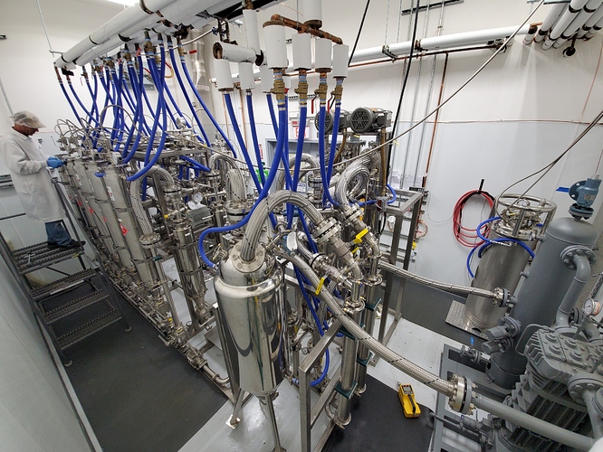
For the food grade direct (R-507) refrigeration heat Ex see pg 2 of the spec sheet for a picture:
https://www.greenprocess.solutions/2020/01/13/40-ton-refrigeration-system/
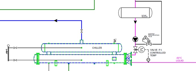
The heat Ex is double pass and uses seamless 316 tubing, and has ASME and CRN numbers. It can be optionally electropolished for an additional 26,430.-USD
See example PID below:
I’m confused by your CNG vs LNG analogy.
When you talk about CNG being better for small scale and LNG “dominating” at large scale, what exactly are you talking about? Fleets of vehicles? Or the general transmission and storage of natural gas on a global scale?
Either way your association of pumps (CNG) with smaller capital costs and smaller scale doesn’t seem to make sense here.
Recovery rate (speed) is generally not determined or provided by any pump/compressor or lack thereof. It’s determined by vapor generation in the evaporator or collection pot.
A pump that’s undersized will act as a restriction but a pump that’s oversized will generally not increase recovery rate although there may be some minor “scavenging” effect like a car’s exhaust manifold.
The recovery setup of an extractor is all about overall system design and workflow.
Generally at smaller scales in cannabis extraction the recovery pumps used (TR21, CMEPOL) often act as a major restriction due to their small pumping capacities and people see an increase in recovery rate switching to passive but sacrifice certain operating abilities.
Fluid characteristics and flow characteristics are two different things.
Just because the fluid itself is compressible, doesn’t mean the flow is.
Whether or not a flow is considered compressible is directly related to the value of the Mach number (speed) of the flow not the properties of the fluid itself.
Mach number is the ratio of flow velocity past a boundary compared to the speed of sound in that fluid.
Choked flow only occurs when the exit velocity from the orifice is at or very close to Mach 1, or 100% the speed of sound in that fluid. This is related to the critical pressure ratio across the orifice like you mentioned, but where are you thinking this is occurring in an extraction system? Why do you think the inlet of the pump would cause this?
I don’t see how the inlet to the compressors used in extraction would cause choked flow as you describe.
I think it’s possible you might be confusing choked flow through an orifice with compressor choking or stonewalling. Compressor choke is a property of dynamic (centrifugal) compressors, not positive displacement compressors like the ones we typically use in extraction.
Although some people erroneously think so, a gas compressor (pump) is not used in an extraction system to speed up recovery rate.
I agree that it’s very important to not have any restrictive orifices in the vapor recovery stream. The typical Swagelok GS series process valves that are used do indeed have a restrictive orifice size at the larger connection sizes and I make sure to use 63 series or full port valves on my vapor side to avoid flow restriction.
I’m not saying it’s impossible to have choked flow conditions in extraction systems, especially huge falling films and very large collection pots but I think it’s very unlikely.
Compressible flow and choked flow seem to be more an issue in high speed (mach 1) aircraft, jet engines, rocket nozzles and high pressure gas pipelines (I am familiar with orifice plates).
I would say this really depends on the specific situation.
For a very large batch or continuous system with intermediate tanks and falling film evaporators it could be a good choice to just go passive. Just like for ethanol and other hydrocarbons.
I personally think that for batch systems up to very large batch sizes that want to rely on a one tank closed loop system (recovering into the same tank you flood from), it will be simplest and most efficient to have a vapor recovery pump in the loop, probably as part of a hybrid recovery setup.
I think the real answer for ultimate efficiency with a balance of overall system ease of workflow and recovery rate a hybrid recovery circuit would be the best choice, see my post in the other active/passive thread.
There are definitely periods during my (active) recovery toward the top of the bell curve of the difference between vessel pressures where a passive circuit would make sense to add and I have pondered putting a simple bypass line with a one-way check valve around the pump to take full advantage.
As systems and vessels get larger, I think it becomes more difficult to keep the entire volume of solvent at low enough vapor pressure on the recovery side to keep up peak passive recovery efficiency. Not to mention vapor assisting. This is all compounded if the operator wishes to use a high propane mix.
I think your assertions about noise and hazards from recovery pumps and air compressors is somewhat moot. Obviously some people are more sensitive than others but I have worked in shops my whole life and don’t have any problems with these issues. I know the old Haskel’s can be a little loud in the operating booth with all the knocking but pumps like Corken, Blackmer and LeRoi are very quiet pumps and not a problem at all.
With respect to teflon and metal shavings, I don’t think the effect is really that bad. Especially with a proper pump like a Corken that is actually designed to pump hazardous gases like ammonia for years and years. A diaphragm pump like an MVP is probably even less prone to shedding contaminates.
Also, most extracts are filtered down to 1 micron these days with the advent of CRC which would handle any detritus that would find its way in.
Honestly, I think most contaminates come into the system on the input material itself.
I remember I was out in the hills one time and I saw some guys working on a greenhouse frame around plants and had to take a grinder to something they were working on. They had setup a blanket to act as a shield but I’m sure some metal shavings made their way onto the plants.
I understand that you’re trying to do some marketing here for your company and that’s all good.
It’s not a surprise to me that a mechanical chiller will be cheaper over time than a constant consumable like liquid air gases. That seems very obvious and I don’t think anyone is debating that fact.
However there are still several arguments for why someone would want to stick with liquid air gases over a mechanical chiller like financial ability, equipment reliability, electrical hookup availability, ability to modify the existing building, etc.
Marketing this from the angle that chiller systems like the ones you offer save money in the long run vs a constant consumable makes sense.
I think using this logic to say that passive is a better or simpler option for batch extraction systems is a stretch and may be the result of some confirmation bias you have toward the products you’re trying to sell.
The active/passive debate is much more about workflow design, throughput and system design simplicity, IMO, than it is about overall recovery rate.
Respectfully, you are incorrect dear sir.
I dont have the time/energy to respond to your entire post.
Please review my underlying calculations if you wish, specifically:
https://www.instagram.com/p/B4ZTOKch4Vl/
Which uses formula for Mdot found here:
I maintain that most if not all extractors passive or active experience flow choking.
Review the numbers below, tell me if you can find fault with them:
Nomenclature:
Mdot = Mass flow rate [g/s]
M = Mach Number [Dimensionless]
γ = Ratio of specific heats [Dimensionless]
P = Pressure [Pa]
Rho = Density [kg/m^3]
u = Speed of gas in the pipe [m/s]
c = Sound speed of the gas [m/s]
Cd = Coefficient of Discharge [Dimensionless]
Cv = Flow Coefficient [Dimensionless]
A = Orifice cross sectional area [m^2]
k = (1.094) Butane, Propane (1.13),
Example Pressure P0 = 206,843 [Pa] (30 psia)
Example Density ρ = 5.29 kg/m^3 (5.29 g/L)
Example Area (for 0.5” Dia) orifice A = 0.0001267 m^2
Example Cd for smooth surface Cd = 1 (ideal, typical values 0.8-0.9)
I understand your point about confirmation bias, and yes at smaller scale a pump may be more expedient, however analytically speaking I have not found a valid counterargument to my analysis in your post.
Respectfully,
I get it man. I’m busy over here too.
But you did have the time/energy to write out your whole OP.
And time to bump up other active vs passive threads while pointing people to this thread to buy your chillers.
If you pop up on the scene one day and make some new claims, it would make sense for you to respond to a rebuttal of your claims. Especially if you’re selling something.
Why not at least explain the CNG vs LNG thing?
I don’t think you’ve really provided sufficient evidence for a lot of what you’re claiming here.
Your OP just kind of stumbles into the idea of choked flow out of nowhere with no real context.
This is sounding a little like charlatanism to me. Or the confirmation bias thing.
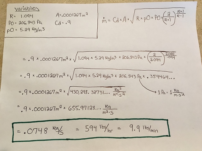
Below is my work solving the given equation using the variables you provided for a 1/2" orifice in your last post.
The answer I get for max (choked) flow rate of butane vapor through a 1/2" orifice is 594 lbs/hr or about 10 lbs/min.
That’s not too bad by current industry standards for medium/large batch butane extraction systems, active or passive.
Most aren’t even close to that limit but some are.
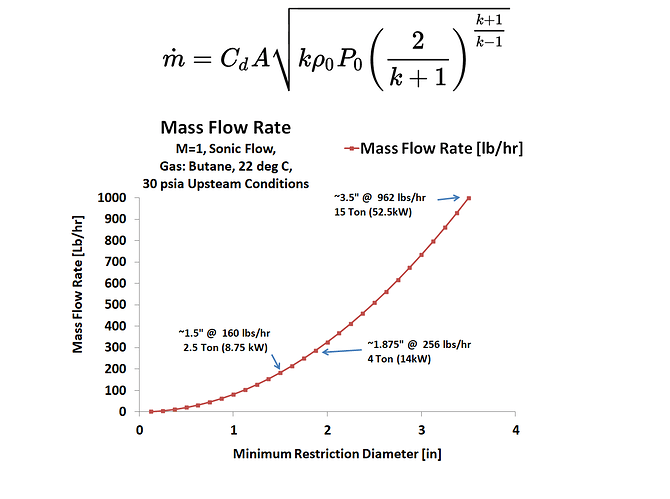
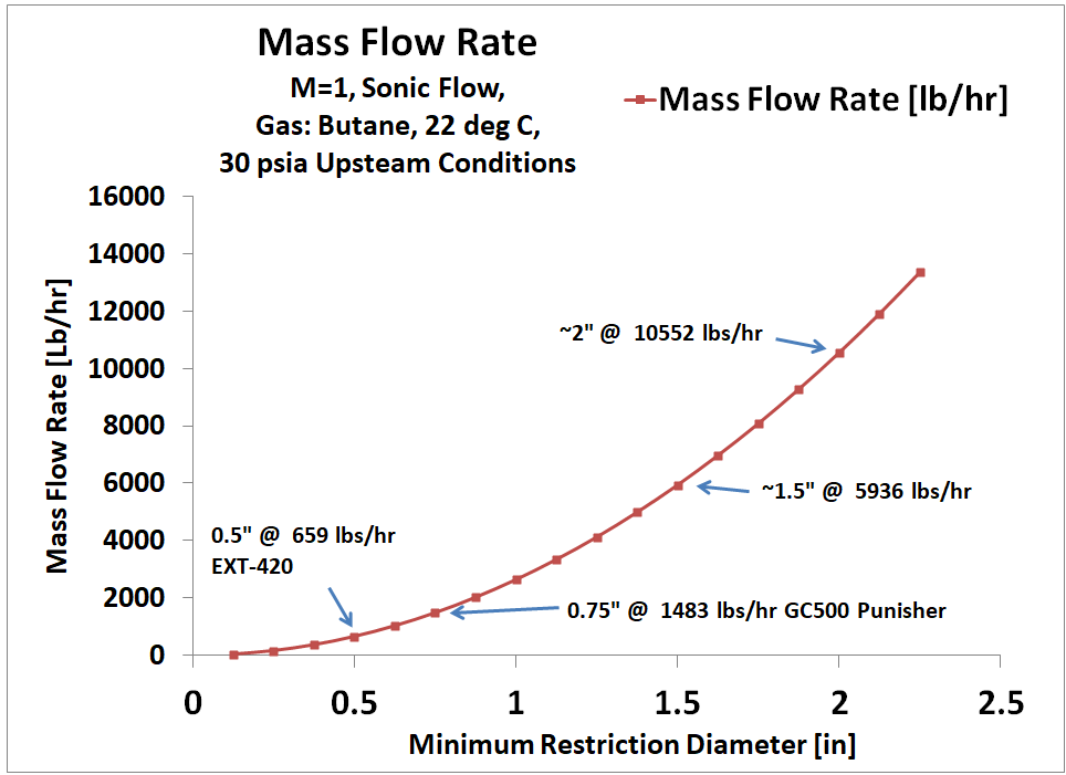
I’m very confused by your chart.
For example, it looks like you are implying that the choke limit for butane vapor through a 1.5" orifice is 160 lbs/hr or 2.6 lbs/min.
If I solve the equation for a 1.5" orifice size (.001142 m2) using your given variables for pressure and density, same as I did above, I get about 5,351 lbs/hr or 89 lbs/min max butane vapor flow rate through a 1.5" orifice.
Why does your chart imply that the limit is only 160 lbs/hr (2.6 lbs/min)?
Your right,
re-did the calcs by hand, for a 0.5" orifice I got 0.083 kg/sec.
I clearly messed up the spreadsheet… and need to redo the chart! ![]()
In practice there would also be friction losses in the lines leading up to the pump as well, so definitely another thing to include in the models.
Tip of the hat to you Sir!
Also, does anyone have numbers for the pressure directly at the recovery pump inlet during operation?
I suspect the inlet pressure at the pump is far lower during operation, if anyone has any empirical data on that?
I apologize for prejudging your response before reading it in depth. I was rather distracted at the moment.
CNG vs LNG
This was just a general analogy to explain that a solution which makes sense at one scale may not be the best once scaled up. The modes of operation are very similar, one process uses compression (which generates heat), and then rejects the heat via heat exchange to atmosphere. The other uses refrigeration to liquefy the gas, both methods can generate the suction needed to drive the process.
On a broader level I believe a passive process without moving parts, and sanitary heat exchangers only is the cleanest method possible, and would be desirable even if the costs are slightly higher.
Use of refrigeration for vapor recovery vs. solvent chilling
The main need for specialized refrigeration is for liquid solvent chilling to low temps, there are already as I’m sure you know many large tonnage UL-listed systems on the market for vapor recovery.
On our flagship model: (https://www.greenprocess.solutions/2020/01/13/40-ton-refrigeration-system/) it includes 2 cooling and 1 heating loop, the -60 Deg C flooded R-507 loop uses 2 stages to reach such a low temperature but provides modest tonnage at that temperature. The -15.6 °C glycol loop runs on the 1st stage and provides far more tonnage. The purpose would be to use the glycol loop for vapor recovery to the solvent storage tank, and then apply -60 Deg C cooling loop just prior to the injection back into the extraction process. Considering the scale of the system, combining it all together provides an energy savings, especially due to the use of waste heat which can be returned to the process. As well as a cleaner integration which only uses one refrigeration system.
Regarding choked flow
Your right, choked flow is only one potential bottleneck in the system. The main issue with many extractors is insufficient heat transfer in the recovery pot (Couldron), this must be overcome with some form of FFE or WFE. (as illuminated extractors have done)
The 2nd major issue is frictional flow loss in the rats nest of long hoses going between the recovery pumps and heat exchangers.
The 3rd major issue would be the limits of the recovery pumps volumetric pumping capacity.
Only after all of those limits are overcome would choked flow become the principal limit, I brought it up because it is one of the lesser known limitations. A comprehensive analysis should look at all of these limitations. And extractors would benefit to know that this type of bottleneck exists, as it behaves in a counter intuitive way in the sense that once P2 is less than ~50% P1 no additional pumping will do anything.
Great write-up! You are completely correct on all of the issues which challenge current extraction systems. It is for many of these reasons in which we designed our systems the way we have.
For instance, our Behemoth extraction system (100% 2 inch piping or larger except for injection lines), butane / propane / mix compatible, can process over 1000 lbs of bio per day into basic crude… More advanced processes such as Live resin can still be achieved with ease thanks to Thermodynamics. We utilize the solvent in way never before thought of in ways which increase the standard efficiency ten fold. We literally got rid of the ratio style of extraction and use a 1:1 bio to solvent. No more the old coffee maker style extraction but instead the more complicated espresso! Paving the way in the industry to the most efficient system possible!
Ok. Great pitch. Got any depth or like… pics?
Lol thank you “thermodynamics” without you we would all be… lost I guess
It is rather funny how much it is mis-understood… we are about to drop new tech across the board.
We completely removed the ratio… 1:1 all day. Can even do with less… +50c to -60c* Capable.
Here is our Behemoth, 1000# per day avg… The only Large Scale Propane / Butane / Mix Extraction System on the Market!! All products capable!
PSI Certified and UL Listing Pending…
U.S. Patent Pending Technology!
Multiple Systems in Operation!!!
Units in stock!
![]()
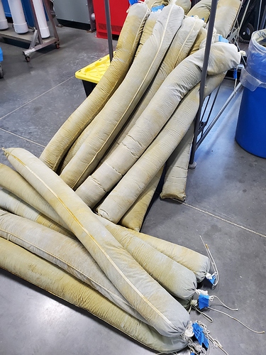
(Tape & Sharpie is applied upon pulling socks so as to track which sock came from what column).
10% bio:
instagram com/p/B7uceV6hIBU/
instagram com/p/B7ucuYgB2hb/
21% bio:
instagram com/p/B8WvCfbBNyz/
instagram com/p/B7g1remhni8/
someone gonna tell this guy what a CLS is? ![]()
It cycles the same solvent through the material until enough is enough?
I am thoroughly intrigued to see this one run
You’re not supposed to extract the tape/sharpie combo.
it appears to work by sending the same solvent through the biomass >>> WFE >> biomass several times, stripping the concentrate oil in the process.
