I use a tall skinny collection pot instead of short fat one and I also recover and inject through the dip tube. Killa showed me once recovery through the dip tube is like having a coil inside the tank bc once it’s get some fuel in it it actually helps condense the liquid faster flowing through the cold liquid
And being tall and skinny plus having the pot setting on a grate that lets ur cooling bath go under the pot also adds another spots to cool down which makes my recovery so much faster I sometimes miss the pour if I’m not just standing there
Yes was basically just bumping the discussion and asking more pointedly. Cause it seems obviously amiss.
I am aware of the bhogart horizontal tank, I found a used one for $2500 Its certainly a decent price.
Exploring other options too though. One would be a new asme 8"x48" jacketed spool for $1450.
In terms of dimensions its comparable. surface area of 384sqinch at half full, vs 336 on the bhogart(guessing a 28" length). Im using 4x36" material tubes, so the volume per batch fits the 8" nicely, filling to approx 6" fill depth on a 8"x48" tube is the equiv of a 17" fill with a 12"dia vertical collection. With a nice 331sqinch@6inch fill vs 113sqinch on a vert 12"
I can get two new asme 8" batch tanks for the price of one used 12" bhogart, so am leaning to the former type of solution.
I also liked your points about evap temps and boosting enthalpy before vaporization.
Horizontal is a step in the right direction, and internal heating coils is getting even closer, but the real leap is just to go to a falling film evaporator for the bulk of recovery and finish off in a smaller pot.
The problem with horizontal is it becomes easier to start bumping your solution, though less important it’d be difficult to keep a good temperature balance across the entire vessel, and without a sloping ‘bottom’ you’d always leave quite a bit of product behind.
With vertical you might need to be 80-90% full to get problems with entrainment or bumping, where in a horizontal tank of equal dimensions that’d probably be a lower percentage before you hit the vertical height limit bumping and entrainment. Of course, you could make the hot side the intake and the ‘cool’ end where recovery outputs from, or even add an entrainment separator, but that doesn’t really prevent the likelihood of a bump.
With coils in the vessel you just have to be sure they are high enough to only be submerged in the solution when it still has enough solvent to easily drip from the coils, taking into account for multiple runs building up if you pour in large batches. If the coils are in the extract when it’s close to finished they risk cooking the extract onto them over time and they’ll increase the surface area, not just for heat transfer, but as mentioned before for transfer loss during pours as well.
Each of those improvements are about increasing surface area and a vertical shell and tube system is the culmination of that. You get increased surface area, and reduced residence time giving you both more efficiency and more control over the temperatures you expose your extract to.
Though I don’t have any direct evidence available offhand to support it I also think pulling the vapors from below the point they’re being generated at will help increase flows by reducing the back pressure that usually builds up in the collection when it’s the only source of recovery.
If you fill the horizontal 8x48 up to 6" there won’t be much headspace in there so you’ll probably need a liquid/vapor separator in the recovery path. For reference, I run propane with a Corken on a 12" wide collection pot and usually have a solid 4-6" of frothy bubbles on top of the liquid level during peak recovery. I like to have a lot of extra headspace in my collection pot, don’t you think you’re cutting it a bit close and increasing the chances of sucking solution into the recovery path?
It sounds like you’re thinking about doing the full recovery in the 8x48’s. If that’s correct what are you thinking about doing when it’s time to harvest the oil out of it? Seems like it could get a little messy and time consuming with the horizontal orientation (have to stick your arm in there 24"). I have seen funny pictures of guys having to reach in wearing those full arm-length gloves. I think I saw one with the guy’s arm wrapped in saran wrap or something. Terrible, lol.
Have you considered using a horizontal vessel as a “breaking chamber” designed to quickly recover the bulk of the solvent but then transfer to a smaller “honey pot” to recover the last bit? Maybe a small vertical 8-10" wide jacketed vessel or something simple like that? I think it would be much easier to collect the oil that way and then use fresh warm solvent to CIP the horizontal chamber when needed.
I’m pretty sure that’s what concentrated_humbold does and I’ve read through the Bhogart info, that’s what they do as well. It’s not a bad idea, depending on your throughput. I’ve always wanted to setup a large system and use a kettle reboiler as the breaking chamber.
Sounds like a good idea to me. I think this will really help boost recovery significantly and should be pretty easy to implement on a rack mounted system. Haha, enthalpy booster is such a great name, big thanks to Bizzy for that one.
For some reason my brain likes a tube-in-tube design better for this job. With tube-in-shell I always worry about having to come up with a way to evenly distribute the flow to all the tubes. You don’t need to deal with that on a tube-in-tube.
Remember how Bizzy had three of the Exergy tube-in-tubes tilted on their side and connected in series to boost enthalpy of ethanol solution prior to his FFE? I liked that a lot.
I’m right there with you vertical guys. I think all distillation apparatuses should have a boiling flask that is straight vertical and the height equal to10 times the of the diameter. I don’t understand why not everyone is doing it. I mean it makes perfect sense if you don’t think about it.
I get what you’re saying, but it’s about applications.
If I have a solution that is not viscous, say for instance a solution that is 20-97.5% solvent, but is temperature sensitive to a degree, I’m better off evaporating the majority of it in a thin film where I can get a more even and efficient distribution of heat with shorter residence times.
Once I get to the point where my solution becomes more viscous and much more temperature sensitive, then yes it begins to be better to have a wider sloped base for final stage evaporation where more efficient methods are no longer suited.
Again all of these are a matter of surface area and solution depth related to the current solution concentration and overall viscosity.
It stands to be mentioned too, if you have 2 vessels of equal volume and one is 12" wide and the other 6" wide you end up with somewhere between 50% and double the surface area(i don’t feel like doing the math again rn)… carry that thought forward to shell and tubes, only calculating the interior of the tubes to determine equal volume compared to that 6-8" tube and you’ve got a ridiculous amount of surface area, a good distributor then gives you access to a much larger percentage of that surface area at any given time in the process.
Of course if you want to stay within 8" TCs even for your shell and tube you’ll be limited there to a shell and tube that probably has equal volume to something more like a 6"(again I just don’t feel like doing the calculations rn), but will probably still have more working surface area than the 8" would’ve either vertical or horizontal because you can’t utilize 100% of the surface area in a batch evaporator.
To easily demonstrate the differences go ahead and grab two test tubes fill both of them equally with butane then take one of them and pour it into a coffee cup and see which one evaporates quicker
Correct, @pangea did only mention adjusting his collection when he revived this thread, but he mentioned it in its capacity as an evaporator. I merely suggested there were better ways to increase his surface area, and more specifically the efficiency at which you transfer heat into the solution as was brought up previously by @Tech1145, to get him his desired results.
Without realizing it you’re proving my point with your example. Let’s adjust your expirement a bit.
We can still take two equal amounts of butane, and for one we will do as you have suggested and dump it in a coffee cup. Let’s do a nice volume here to make sure we get quantifiable results. Maybe we fill the cup half way with butane.
For our second equal portion we’ll need to calculate the maximum volume of the coffee cup and translate that into any number of smaller tubes. The tubes are going to need a distributor cap to keep them vertical, and they’ll need to be leveled. Then we’ll pour our second portion of butane into the distributor cap and let it flow into a coffee cup.
At the end you can weigh the butane in both cups and you will find you have more in the cup that simply sat there boiling than you do in the cup that had the butane reach it by first falling through these tubes as a thin film.
Of course this is ignoring the need for continuous regeneration of the heat being applied in either instance to take advantage of the increased efficiency in heating a thin film over a pool of liquid.
I understand and I agree with your assessment of the mechanism by which it works as I do understand thermodynamics. Unlike you I was under the understanding the that the thread was about people who do not possess ffe as part of their cls.
If you want to give people slightly better understanding of the thermodynamics of what you’re describing we can go ahead and do that.
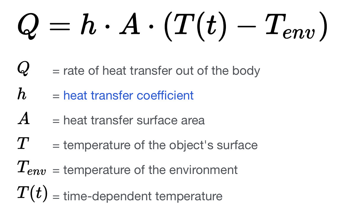
Heat = Energy. An energized particle would move toward entropy / equilibrium in the system and so if you introduce energy to one side the energy will move toward equilibrium on the other side. And so if you energize/heat a particle/energy it will tend to be released out toward the equilibrium in the shortest possible time through the shortest possible way and as such the thinner the material it has to travel through the quicker it will do so, the more surface area in which to release it the more of it will be released simultaneously.
The bubbles are the main concern for sure, I would be shooting for a half fill at most if i was to flood the entire collection, which at this point isnt the plan.
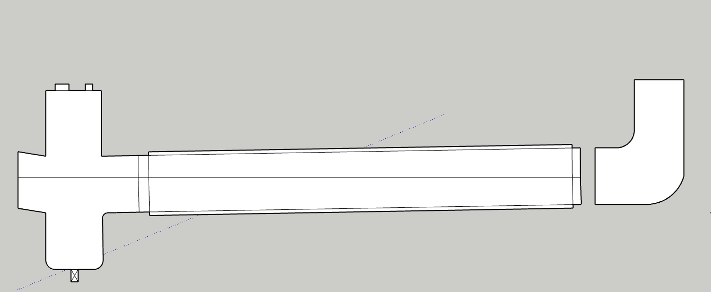
I would have a 6 or 8" cross on one end of the horizontal collection tube, that would serve as lower end collection area, either platter or pour out or redirect to honey pot. The side of the cross would be for a sight glass, ideally a modified cross with a opposite downward tangent slope so no hold up occurs due to the slope. The top of the cross would be for gas recovery path, injection, prv etc, “the lid”. The other end of the collection tube, the high sloped side, could be blanked off, sight glassed, or elbowed upward with an injection port to slope and further thin the incoming solution.
The volume available for foaming or bubble expansion could also be increased with a vert spool on the top of the cross.
pic for reference:
For messy clean up, if necessary my go to is the reflux method that I first came across from one of @SamuraiSam’s many, many helpful posts. Ive used it a few times, it works well.
Ive seen them but didnt know their function. If I understand right, its removing the “specific heat” requirements so we have to deal mainly or only with, “heat of vaporization”.
Which can open the dialog and question to best practices, and why the convo turns to evap solutions like @CuriousChemist22 has laid out about falling films and efficient usage of surface area, etc.
There is a specific thread on the topic,CRC active butane falling film open source. sure wish @Waxplug1 would drop a line or two about their spray lid…!
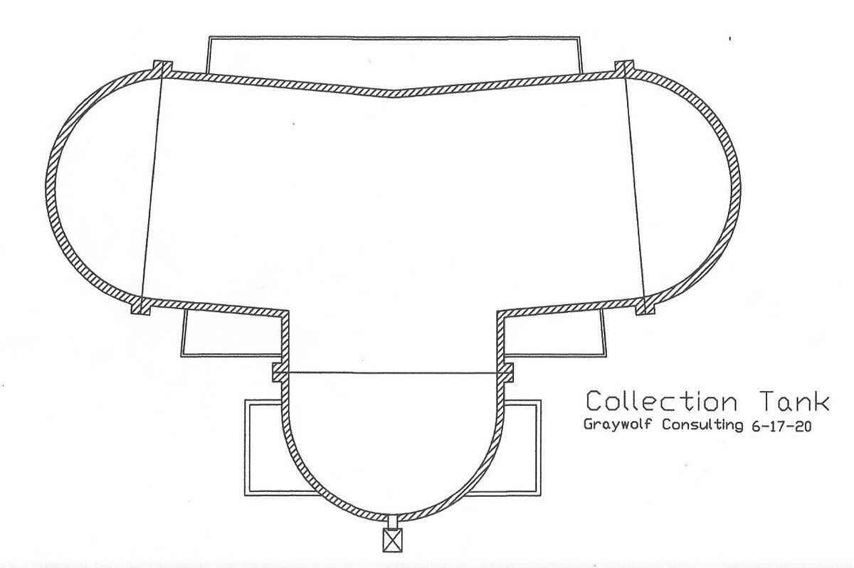
Also, be sure to check out @Graywolf’s concept configuration for a horizontal / increased surface area collection, on his website post 15.6 ASME Pressure pots - GrayWolf's Lair at the end of the article.
That’s correct. Another key part is that the solution isn’t under vacuum while being heated in these coils. This allows us to spray the solution in hot at a very specific temperature, then the instant drop in pressure combined with additional heat from the evaporator leads to rapid vaporization.
I might skip the jackets on the upper portion and put 2-3 (or more) internal heating coils in there. The coils can usually be much thinner stainless than the vessel itself for better heat transfer.
When I was looking over the kettle reboiler design, it definitely struck me that it’s only about a half step away from a true FFE.
Obviously a FFE is probably the most efficient and quickest way to evaporate. For me it’s always been a fear that a FFE would hurt overall workflow if you have to do multiple batches per day and have a highly variable potential batch size. Clearly, if you only do large batches and/or crude a FFE is the way to go I think.
I’ve always had some questions about running a butane FFE but I have never really been able to get anyone running one to talk about it. Top secret info I guess?
If you’re running multiple batches, especially live resin, I’d be concerned with how much oil residue is left in the bottom third of the FFE. I’d imagine as the solvent gets stripped away the tubes will become coated with oil the same way the jacketed parts of a collection pot will. This is important both from the perspective of yield loss on small batches and purity on live resin runs. You don’t want to mix any GMO terps in with your Zkittles for example and if you’re running them back-to-back you’ll want that evaporator very clean to avoid this.
It sounds easy in theory to run a FFE and just clean the residue out by simply flushing it with solvent. I’ve always wondered if it’s really that easy and how long does it take to flush and recover the solvent afterward. Also, on some runs I have had the THCa turn into that ultra sticky cotton candy type of consistency that is very hard to clean/scrape off and I wonder how easy it would be to just flush it out of a FFE.
If I have multiple different collection pots (or honey pots) of different sizes and I can just mount up all to columns for all the batches that day on a big rack and extract each batch quickly into it’s own collection pot and get them recovering while I clean and prepare to harvest them would that be more efficient/faster from an overall workflow perspective than doing each batch individually through the FFE?
Even if you do like I saw you mention in another thread and extract all the batches into holding tanks and then run them through the FFE, would that really be faster than using individual pots that start recovering the instant solution enters them?