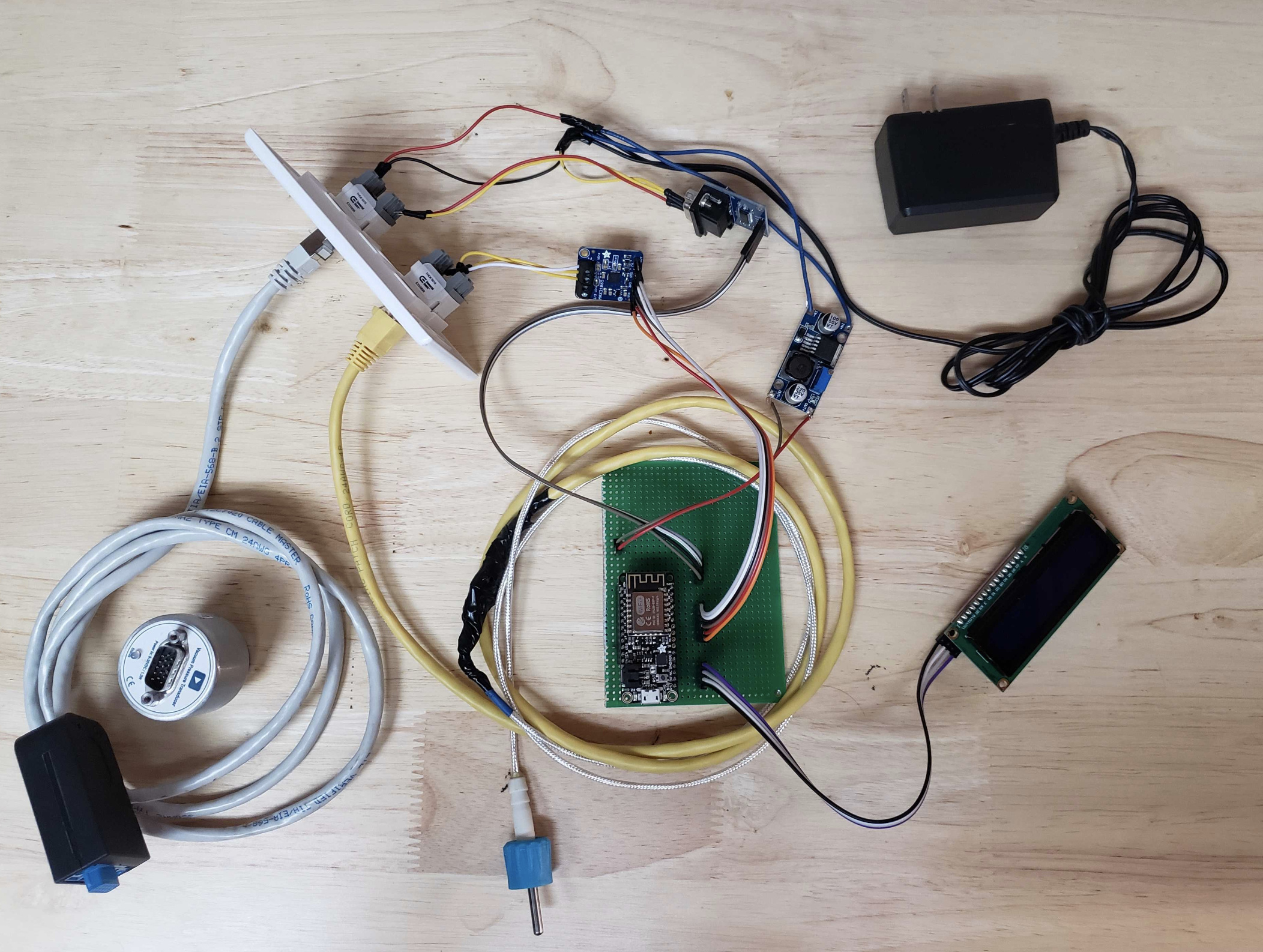
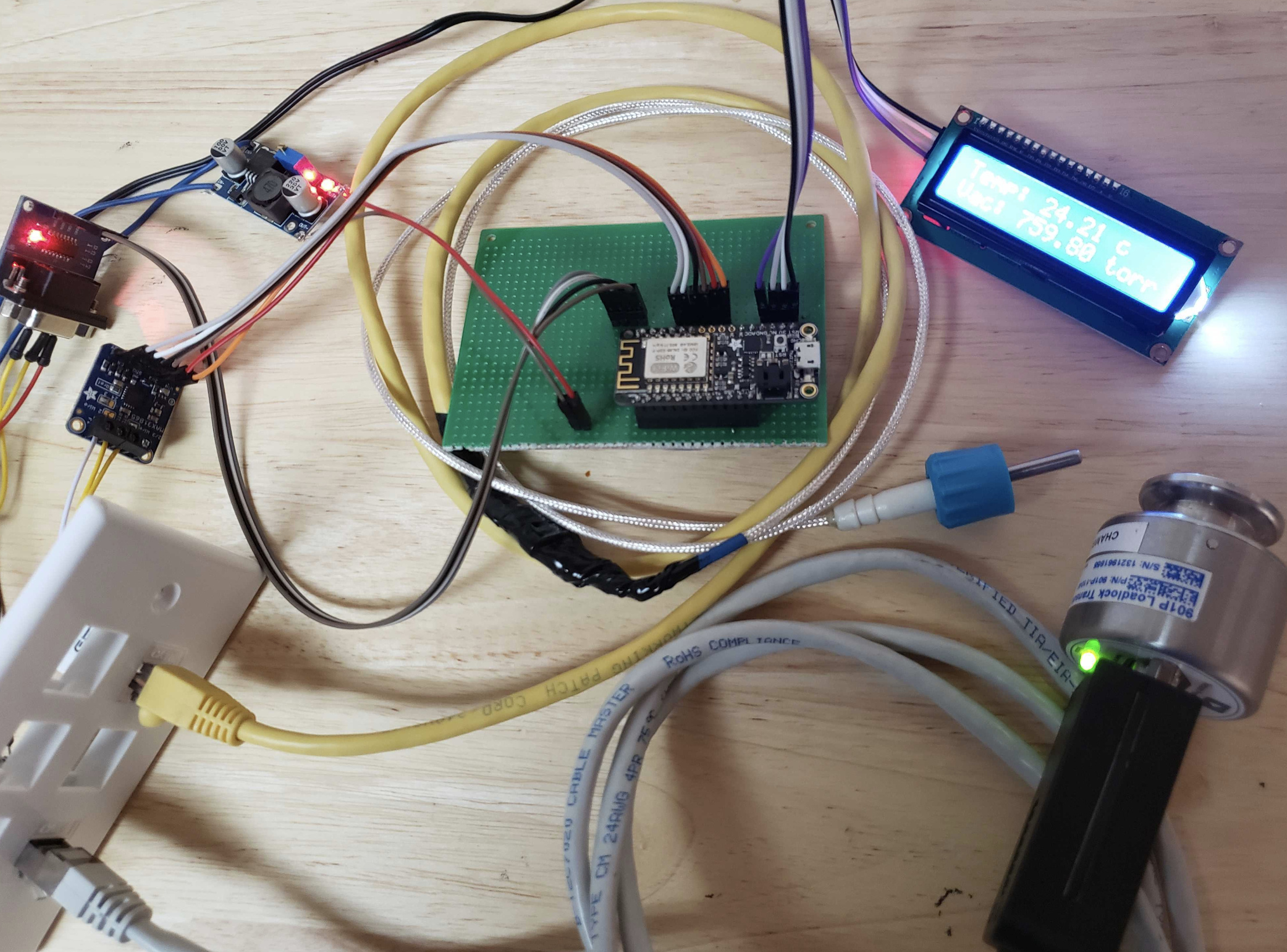
I wanted to get a quick writeup out there so at least the community has something to work off of while I still put together case and circuit designs. Using a list of basic off the shelf components:
AC-DC converter (or whatever gets you a steady 12v dc power source wherever you may be located) (~10$)
Tbh, I havent ran it yet but I hope it holds, haha. I figured I may need to upgrade but this monitor will tell me once I can get a real pump on the system. Any temp probe should work, the hardware/software would just need to be tweaked.
How big of a chamber are you thinking? And do you plan on stuffing it with biomass or would you want some type of rack system to separate layers? With some quick research I think I can do that give a little bit of time.
Thanks, I was inspired by both of those posts. I also am looking to finish building my underlying framework for expanding device options for diy enthusiasts:
I think you can do almost the same thing with a nice cooler and dry ice alone. Layer dry ice and materials, close cooler, and let the dry ice sublimate.
I’ve tried that setup before and it’s more for novelty, can’t do much volume at all with that setup.
I’ve gotten real close to buying a harvest right, but can’t justify the cost for my personal hobby.
I can’t personally say, but I imagine there’s always that possibility, but a good scrub would probably help.
Right before the covid craze started, I was looking into em casually, but then checking their backlog after this shit started made me forget about it again.
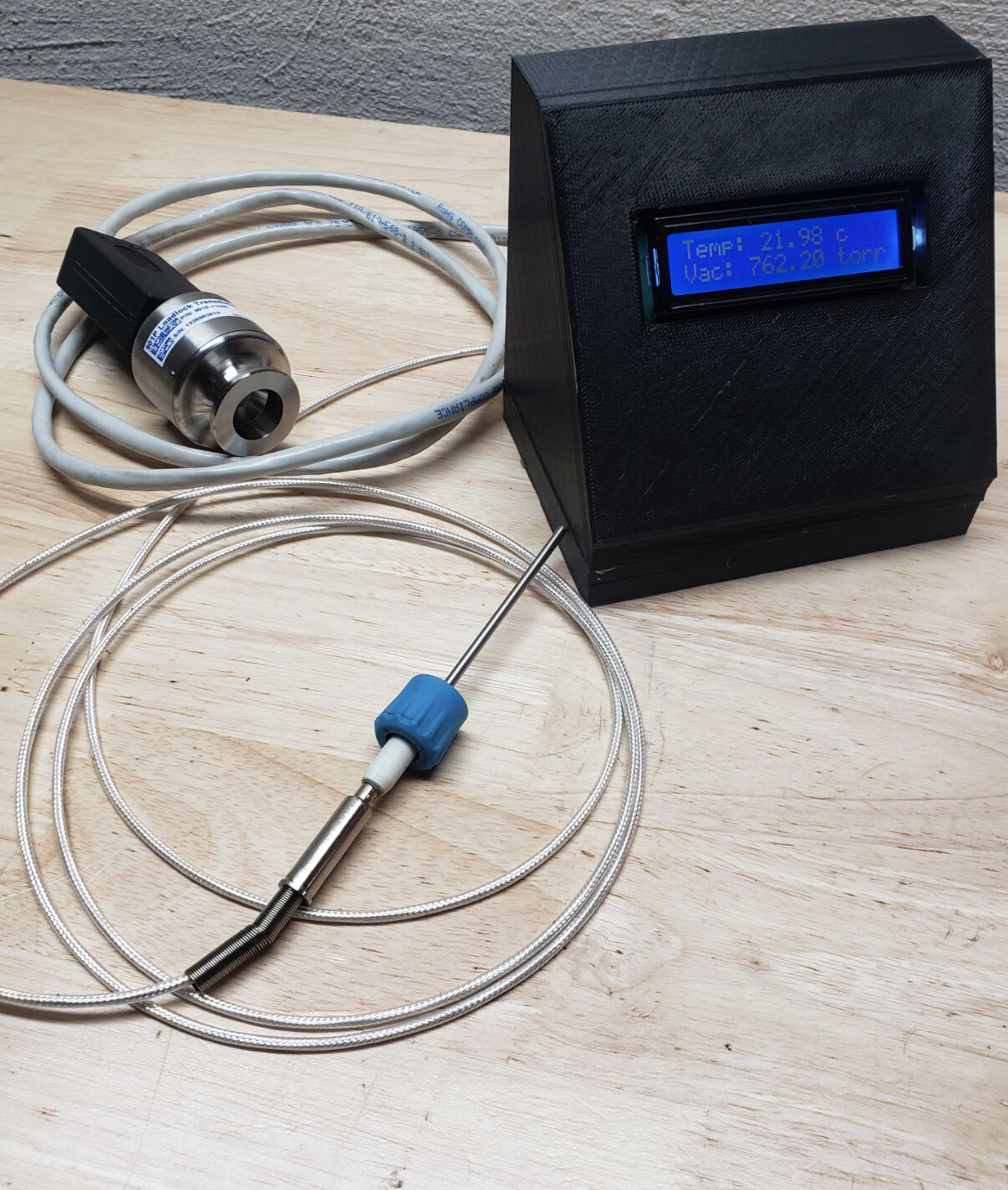
For anyone using this, I had hoped to have time to build out the setup and case more but here is a set of stl files for the top and bottom 3d prints. When I can eventually optimize space and add ability to plug and play sensors or even add a simple mating mechanism between the two halves, I’ll update these models. Prototype case is oversized but looks like this:
Happy to provide fusion 360 project files or other formats for anyone interested. For reference, top took my wanhao i3 about 12ish hours; bottom took about 4 hours. Lots of room to improve but like all projects, I needed it working yesterday… Prototype_Case_Bottom.stl (8.9 KB) Prototype_Case_Top.stl (2.8 KB)
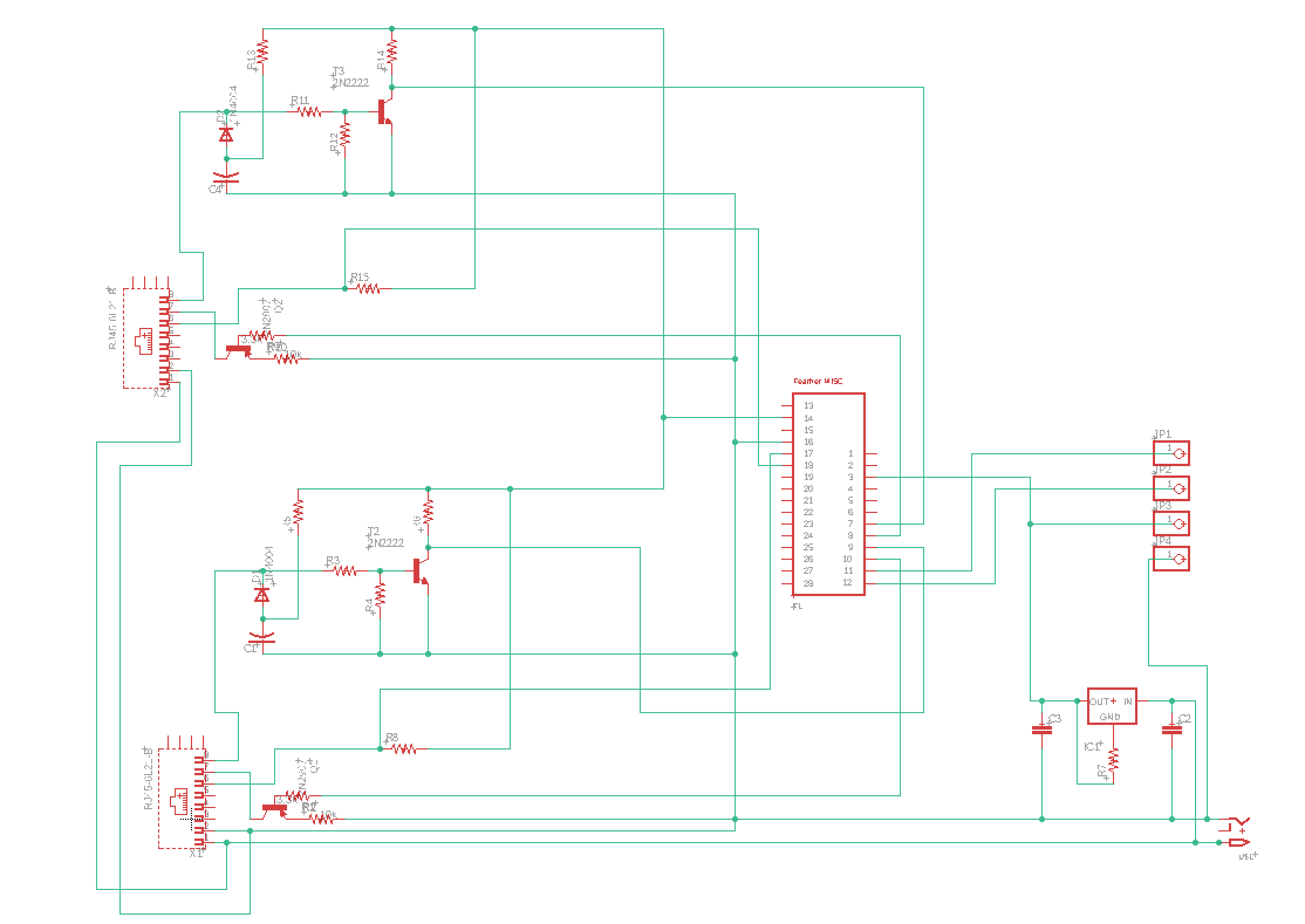
Will need some time to go back and check the traces. In the meantime here is a schematic slightly different than the above that allows for the same end product without having to use modules. Should get you thinking about how to wire it up. Also, if you look at the arduino code, it should have the pinouts for the modules.
I’m connected using standard RS-232 but with a hardware translation for RS-485 I think it would work. I like the serial instead of the analog so I dont need to run a more precise adc and can run with less hardware. Shoot me a dm and I can help guide your specific setup.
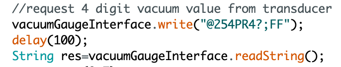
If using an arduino like I am, and you already have the hardware setup to 2way convert TTL to RS-485 then its just as simple as setting up the software to send the required commands and do some serial string parsing:
Starting on page 13, it starts to go into the ‘Communication Protocol’. That will tell you everything you need to know about sending/receiving data from the transducer. If you have the same one, you may be able to communicate via RS-485 as well as RS-232; maybe try RS-232 instead?
My problem has been in the vein of “frame shift” errors. I can, for example, send the code that blinks the LED on the transducer, but when querying for a reading I get garbled strings back.
I’m away from my setup, but will send some examples, and maybe between the two of us make some progress! Digital communications is definitely the way to go with these little guys! I’d hate to have to dedicate a 16-bit (or 24?) A to D card to read these things.