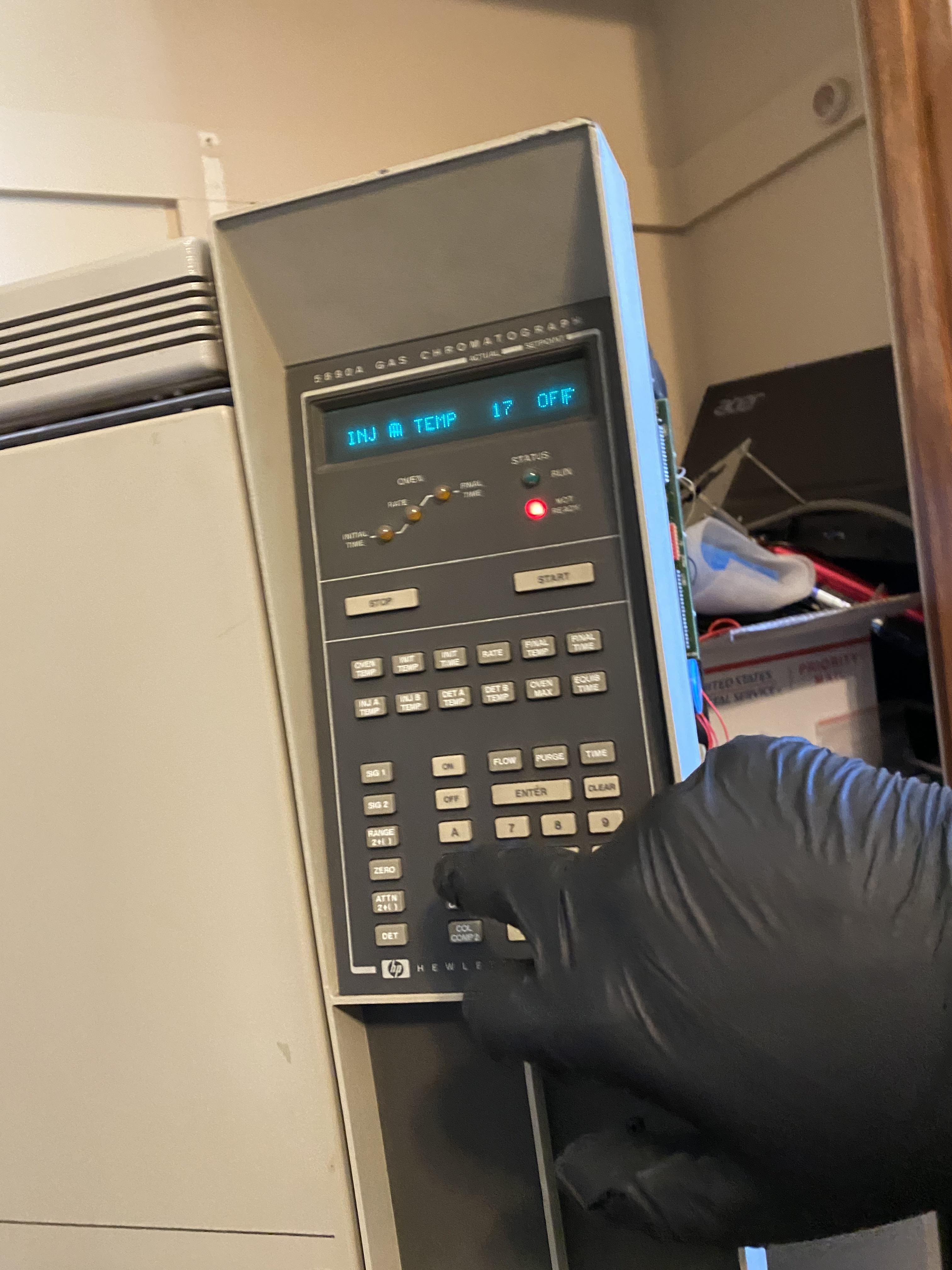
Day two down. Complete rebuild of the 5890 nearly finished, a handful of parts needed after this. What follows is a rough attempt at documenting the process of re installing the FID heater block and other pin outs.
This is the stock split port injector that came with my Series II, I used this as a template for cannibalizing pieces from the parts unit which came with purge packed injectors (whoops).
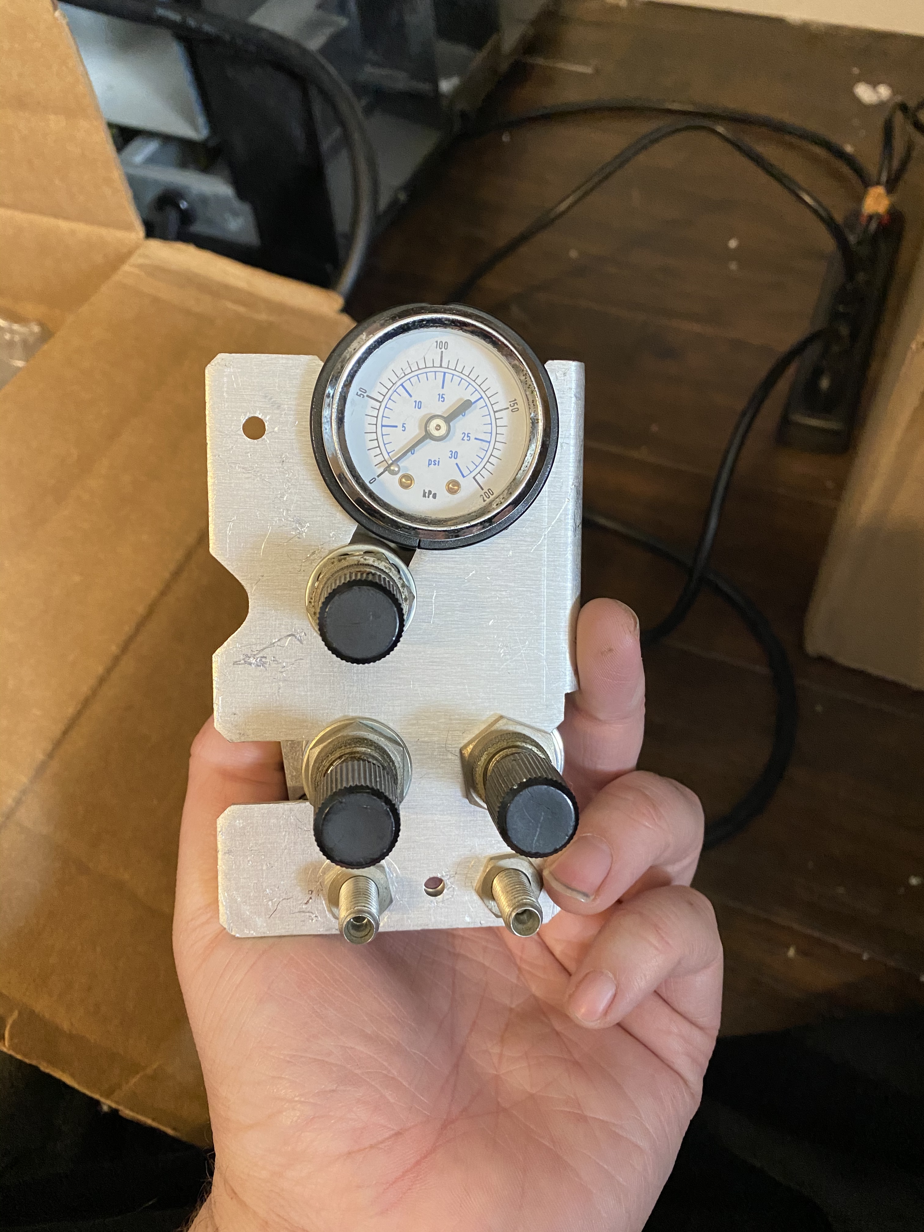
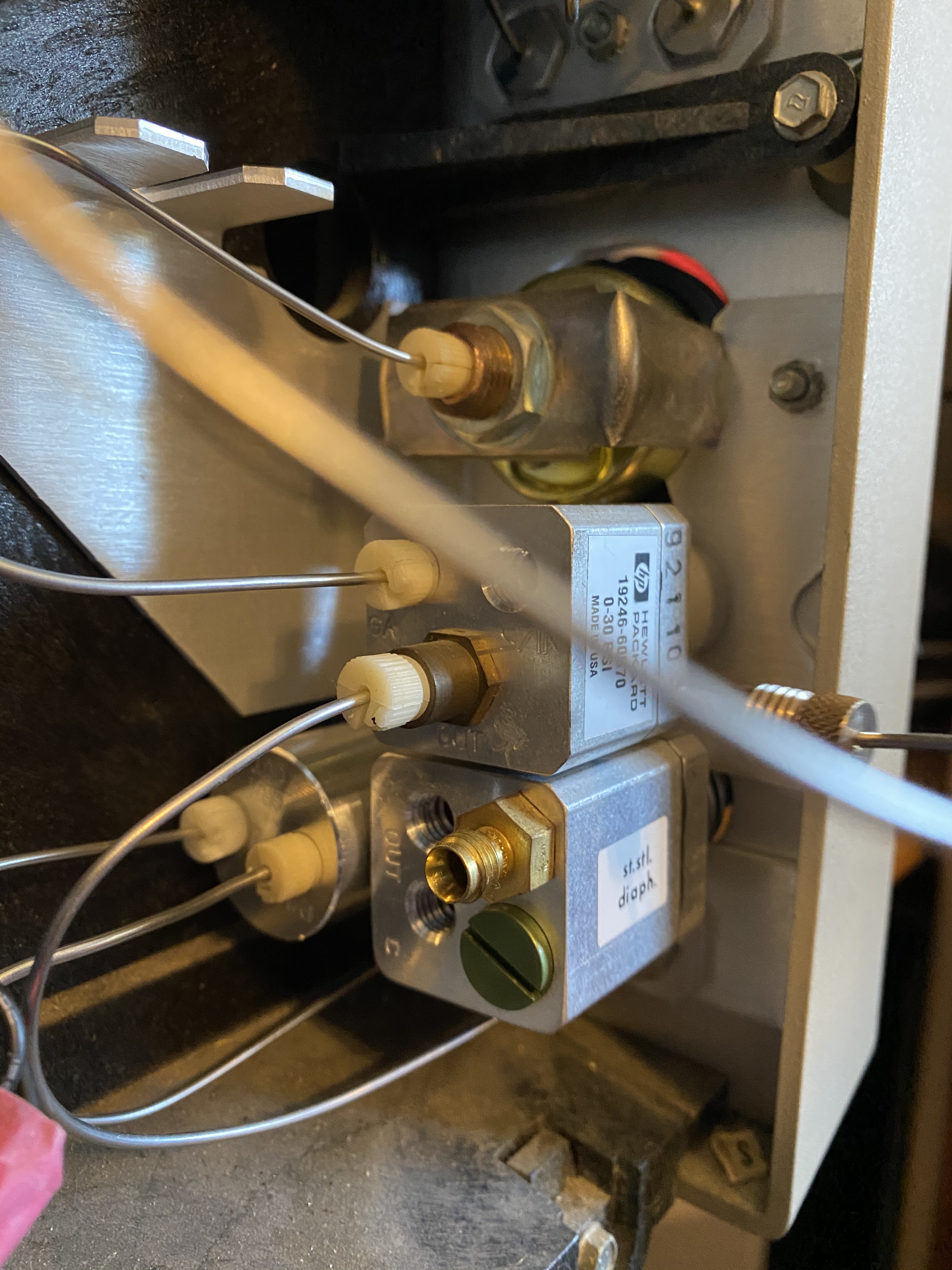
This is how it came out of the parts unit. I would end up disconnecting the regular an copper, from the other manifold in the picture, i would take the purge port (gas outlet port under the 2 black knobs to add to this one. I didn’t want to risk using the wrong part, so I took the part number for the missing regulator and popped that into eBay
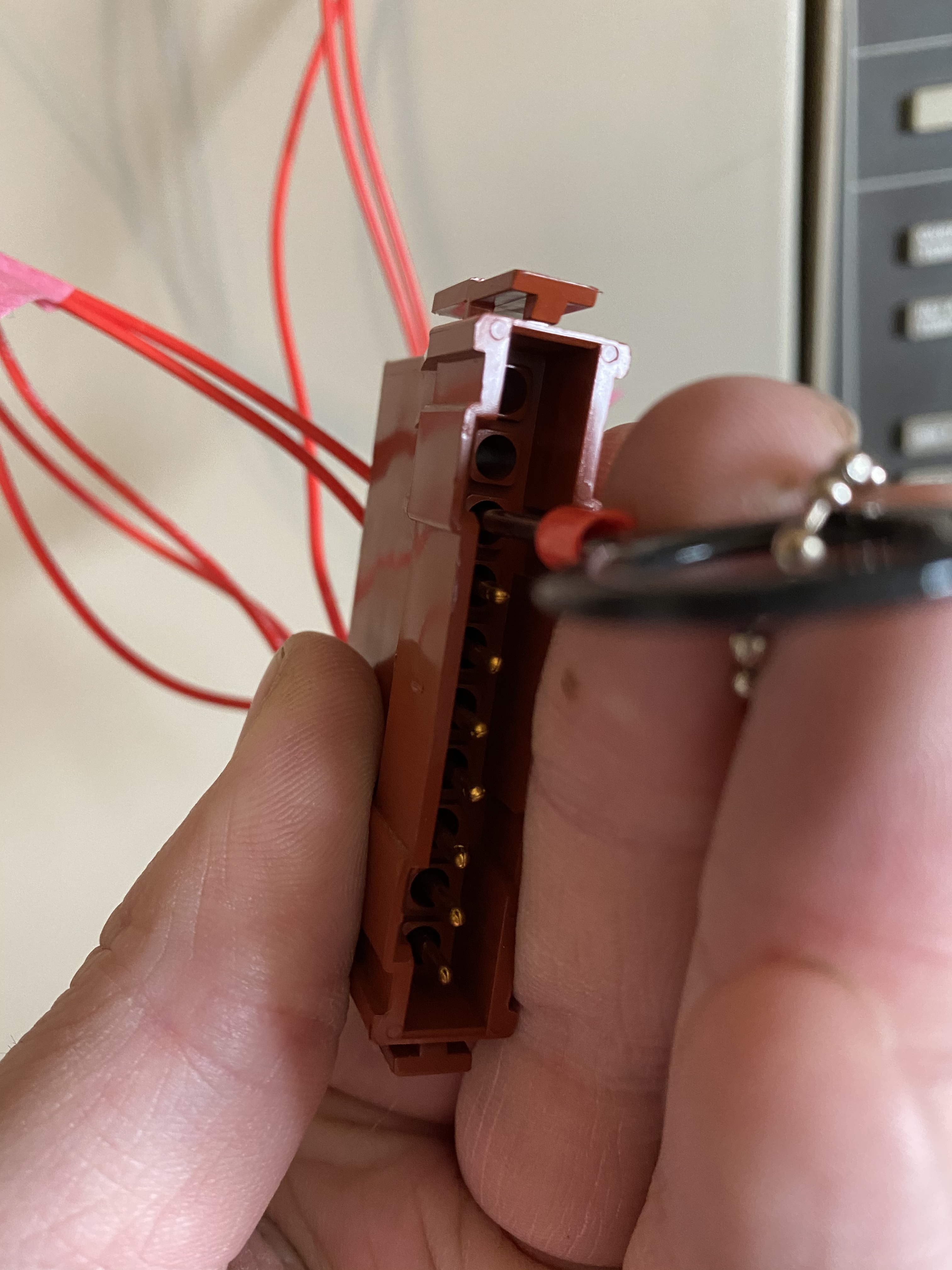
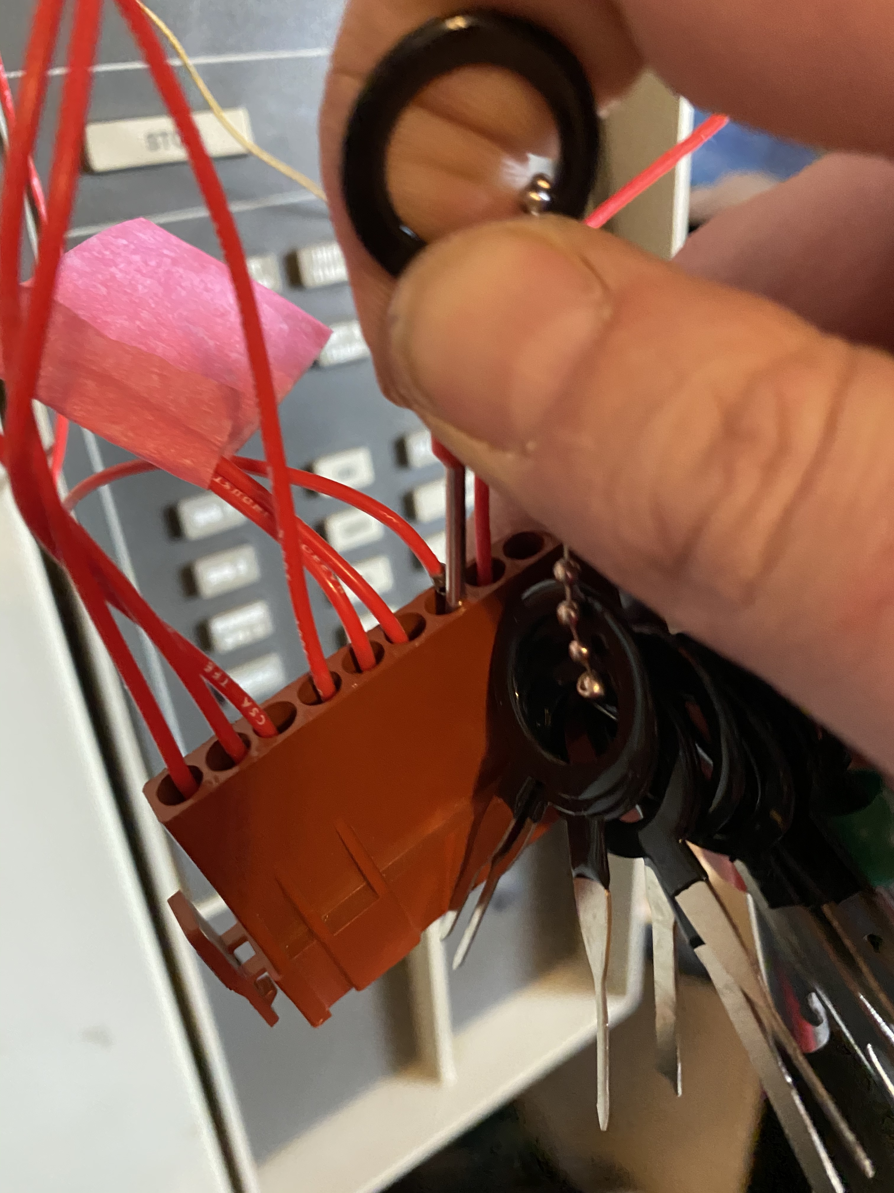
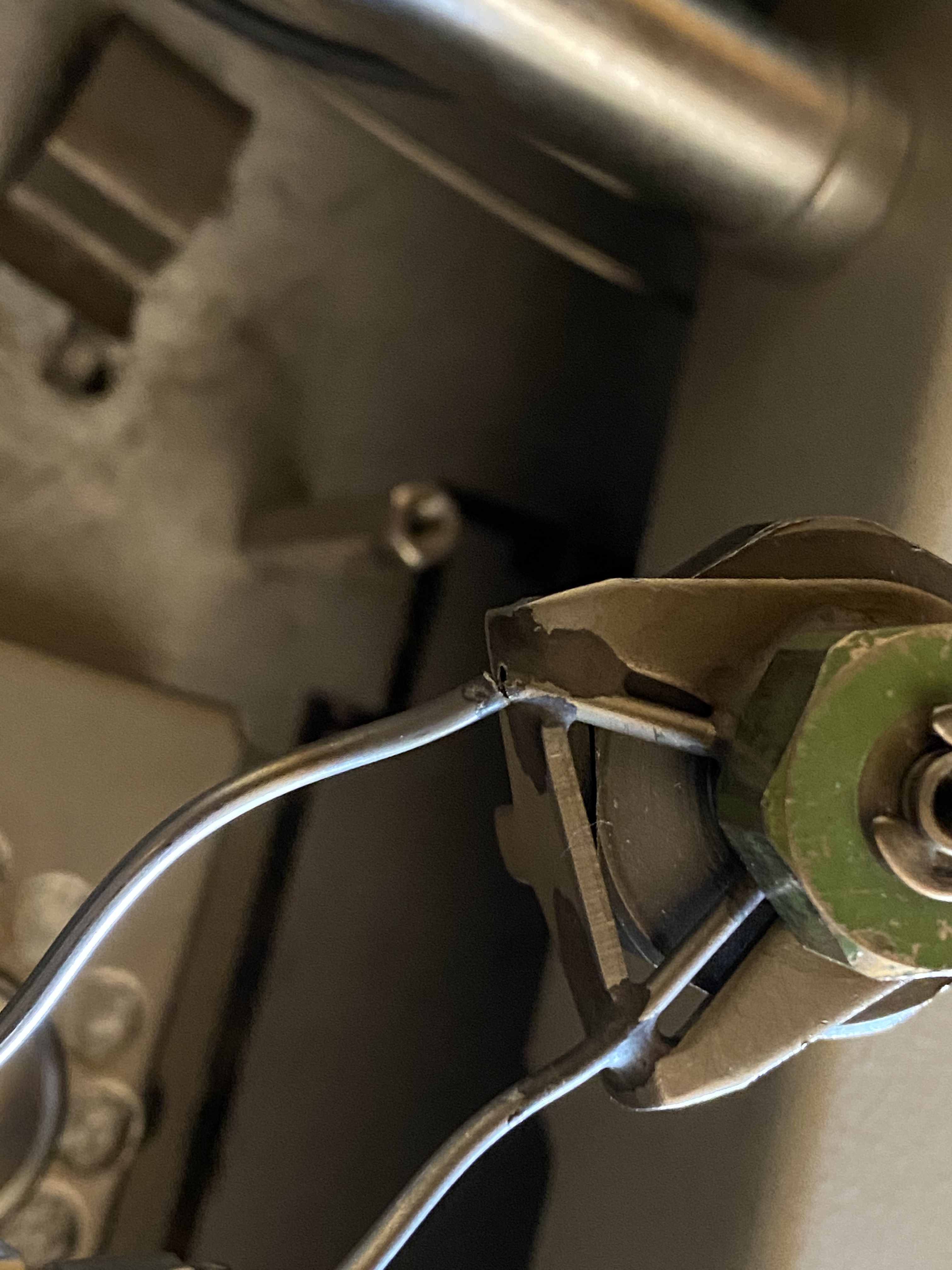
This is the first time I’ve ever re terminated a block like this and I undoubtedly made some mistakes. Best as i can tell, the process that worked for me was to push the key into the pin, with some slight twisting and pressure it would pop out.
Here I am removing the existing wiring for the heater blocks from the purge packed injectors, starting with injector B, and moving to injector A.
I am unclear if the order of the wires matters here. I did not make any effort to track during this process.
Using the tool, push the pin from the new injector block into the terminal block.
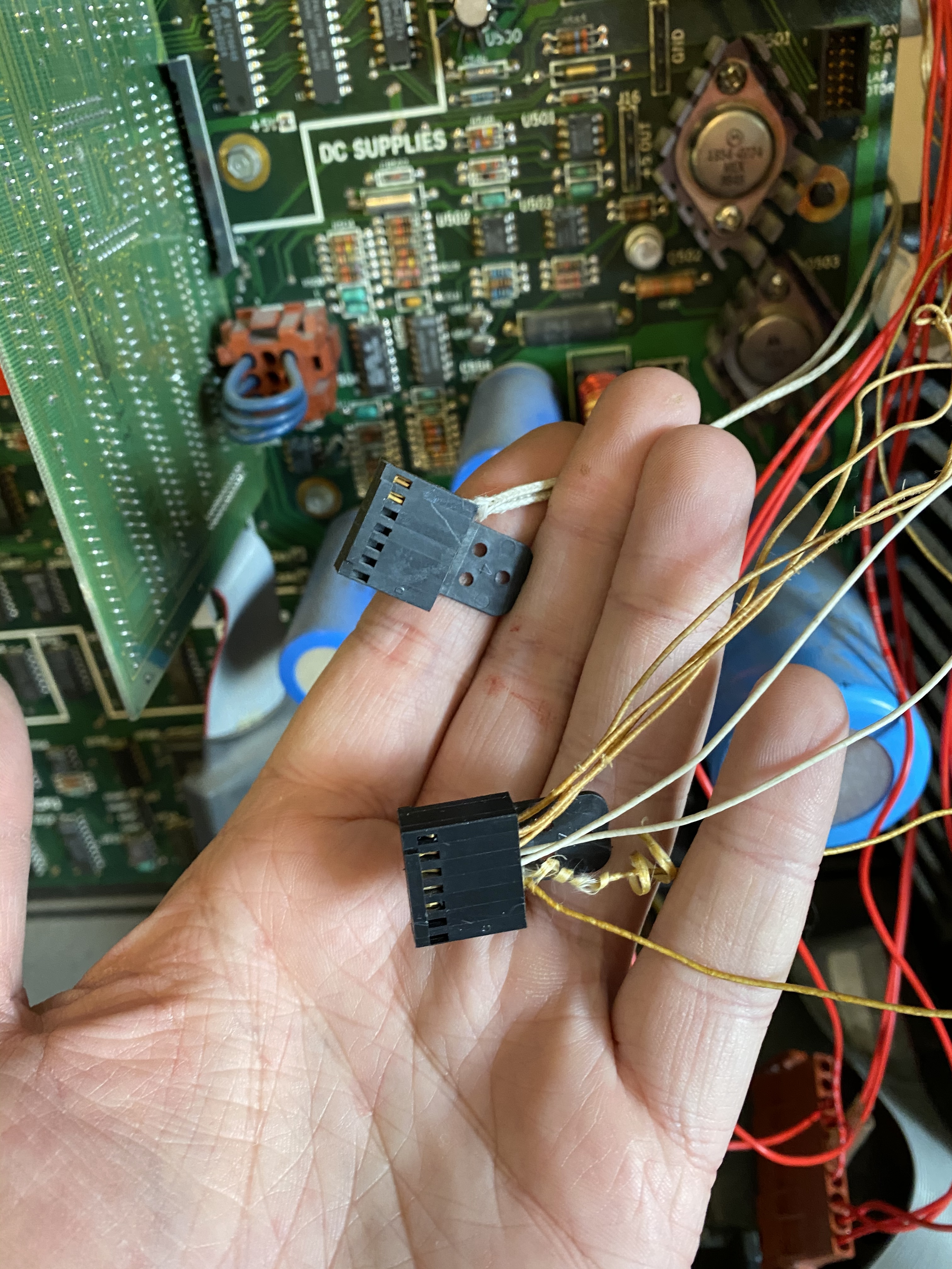
Here I left the original connector block (white two wires on top) which connect to the temperature sensor in the oven, the second block is from the assembly with the two injectors. I will be removing the oven temperature wires and moving them to the other block while also removing the injector wires and keying in the new ones.
Not pictured: i added 2 additional wires for the injector b purge solenoid, and an additional 1 wire for the ignition for the detector b. You can see these wires, unterminated hanging off the right side.
The terminal connectors (dupont or some close knock off) i had did not fit exactly correctly into the existing terminal block. This lead to me having to plug the block in, then the subsequent individual wires to make contact with their pins.
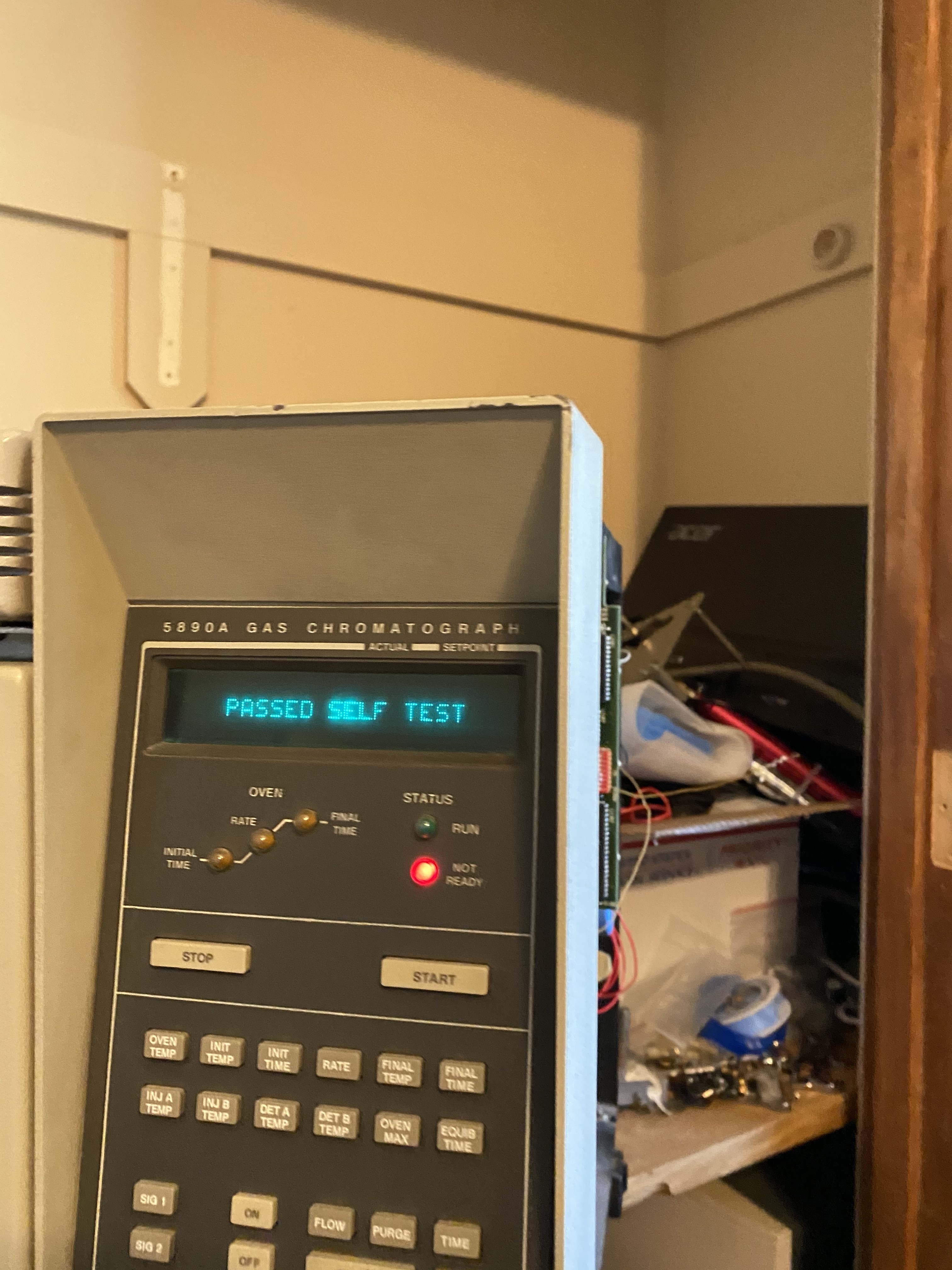
Fingers crossed and a lot of hope that this works.
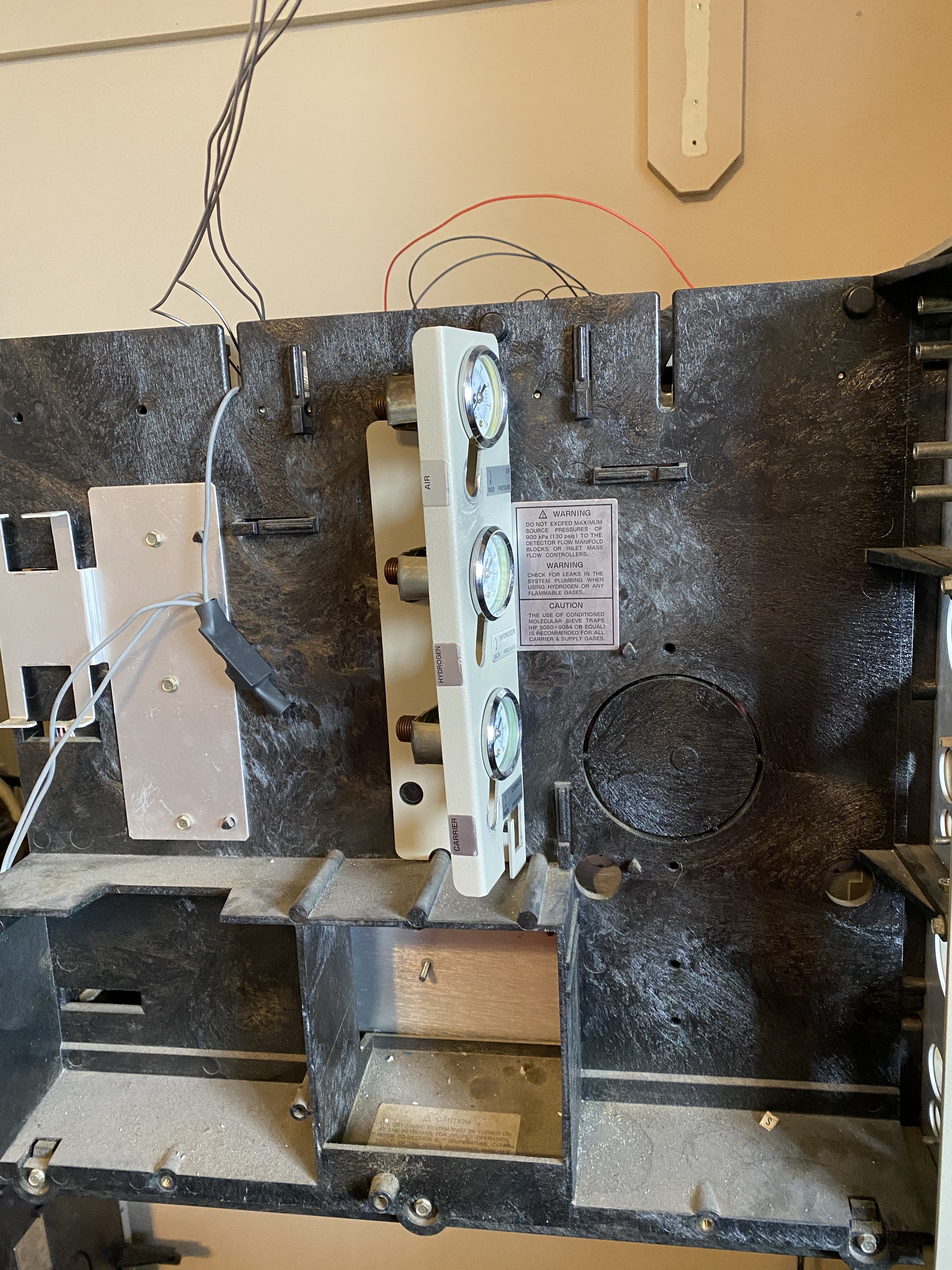
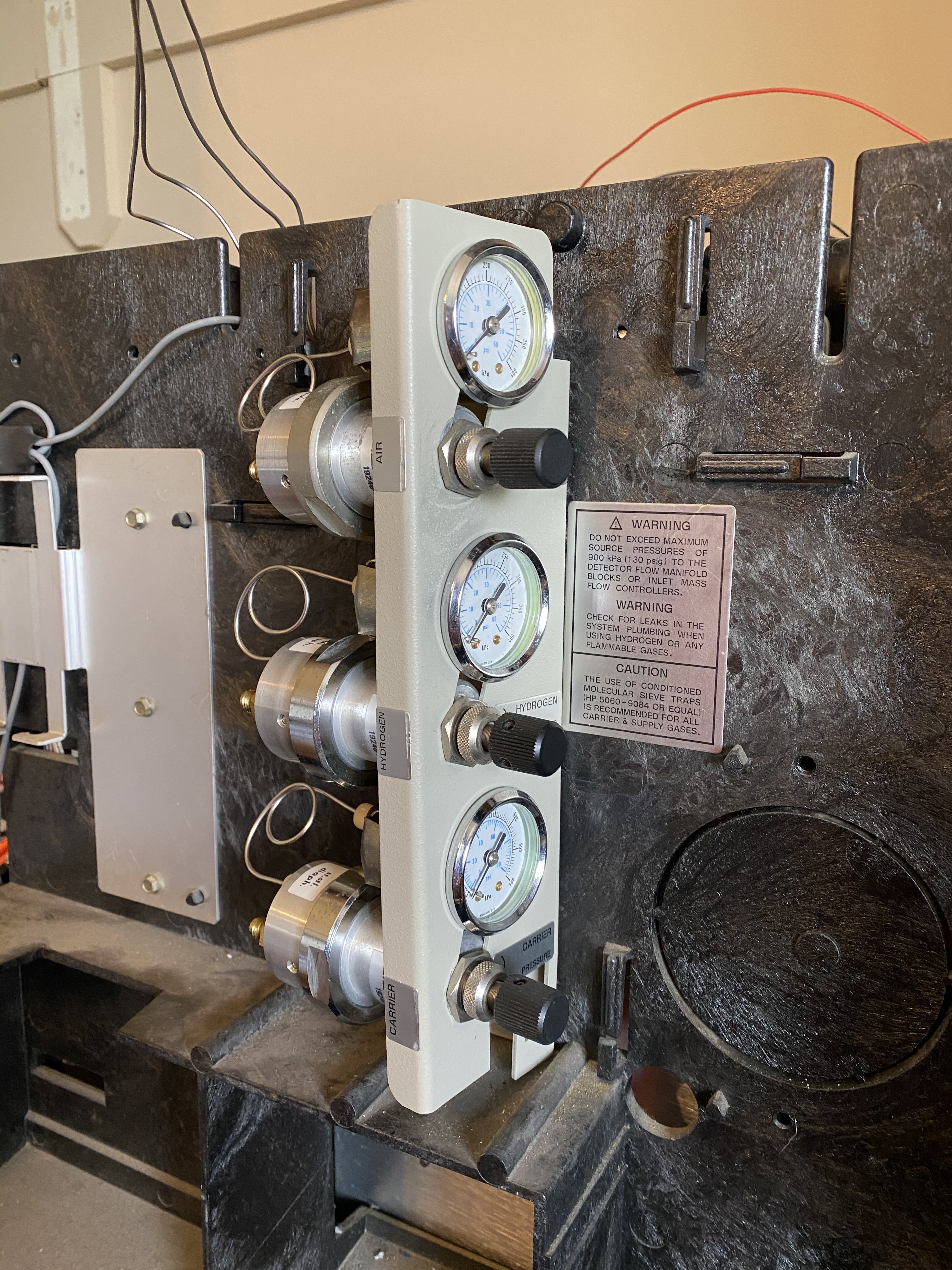
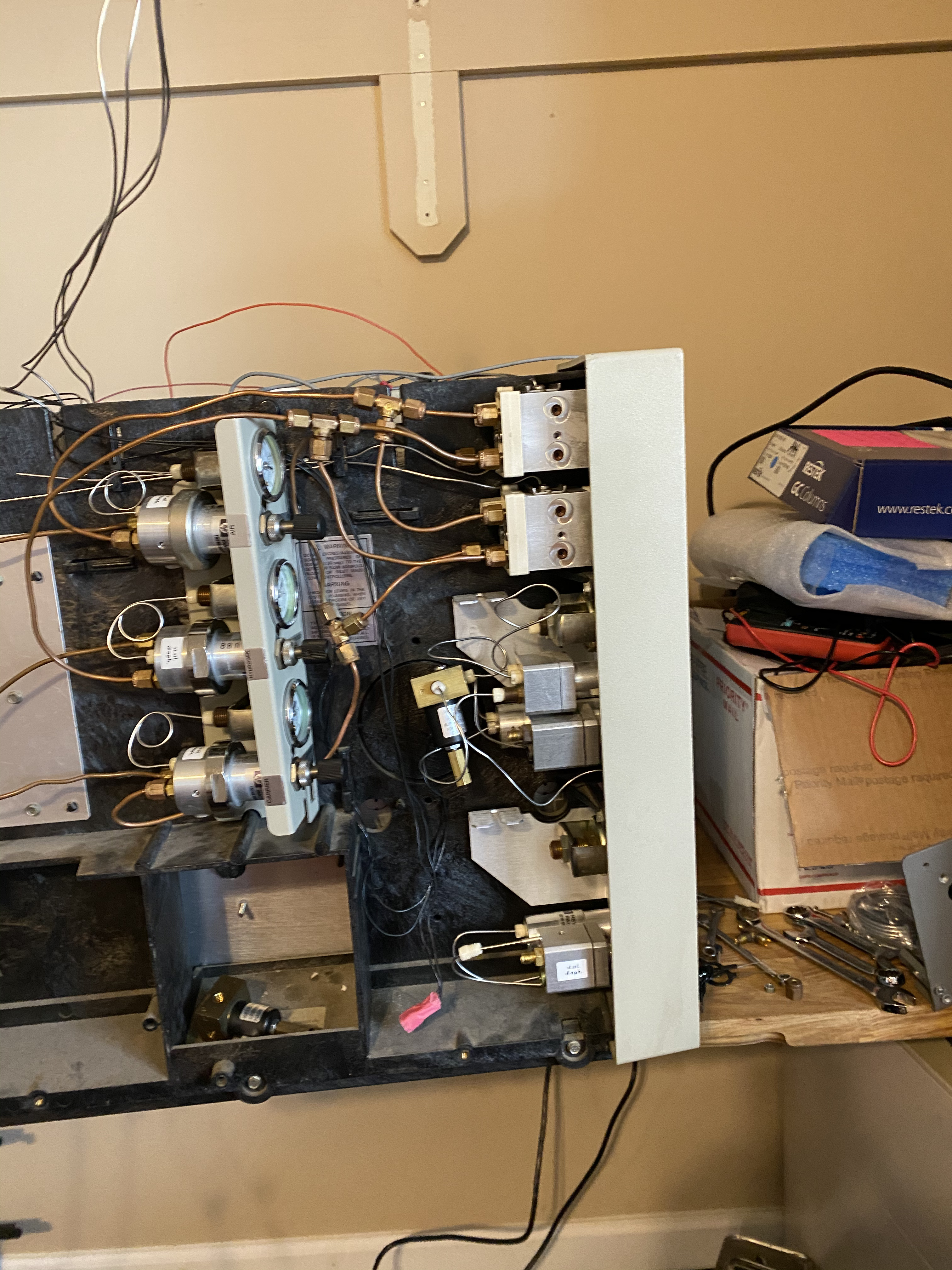
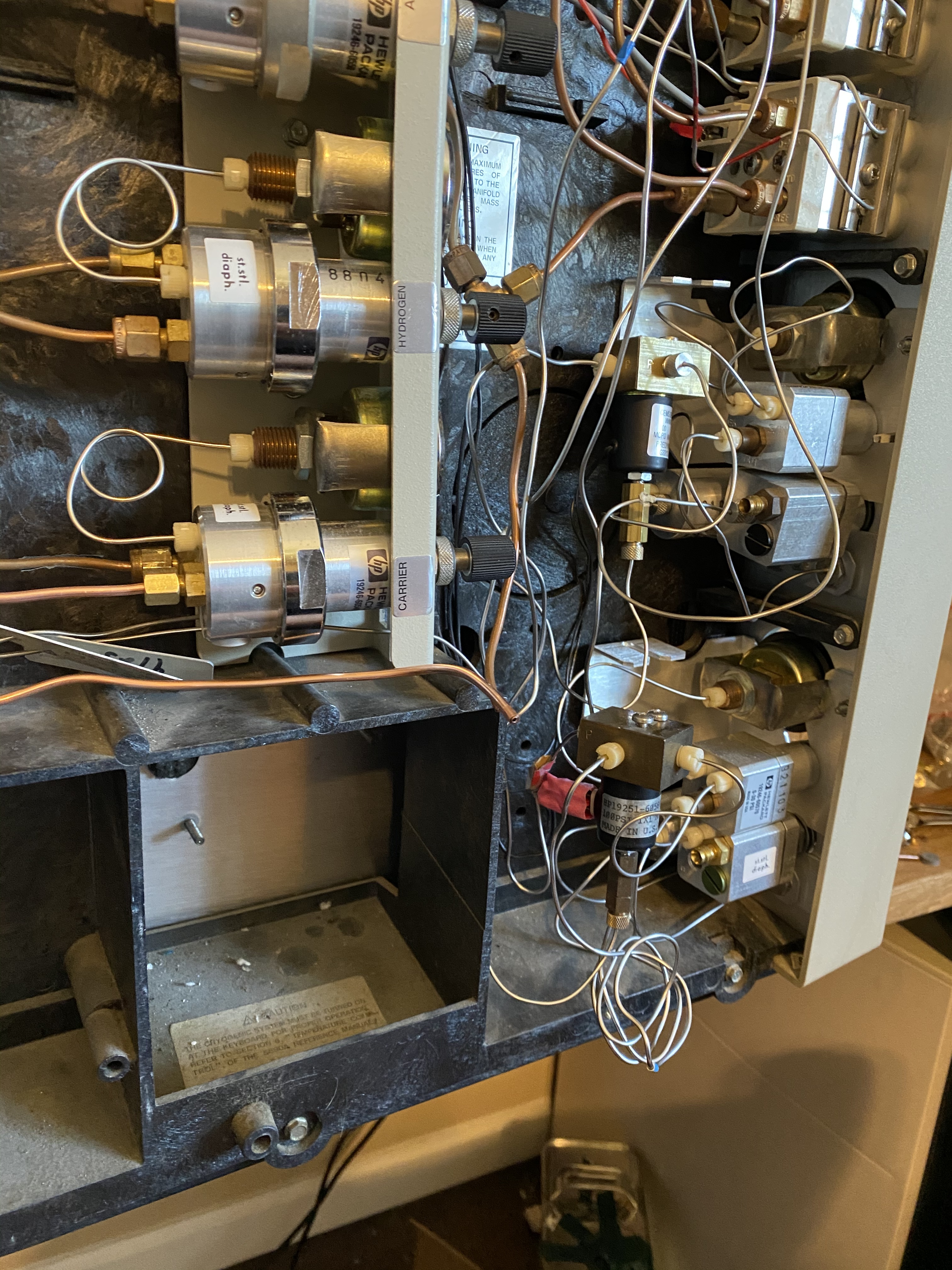
One of the things the parts unit had that my Series II did not have, was this pressure regulating manifold, it seemed like a good idea to add that in. Here the manifold is painstakingly bolted down via a 1/4 wrench. This was a shoulder killing process

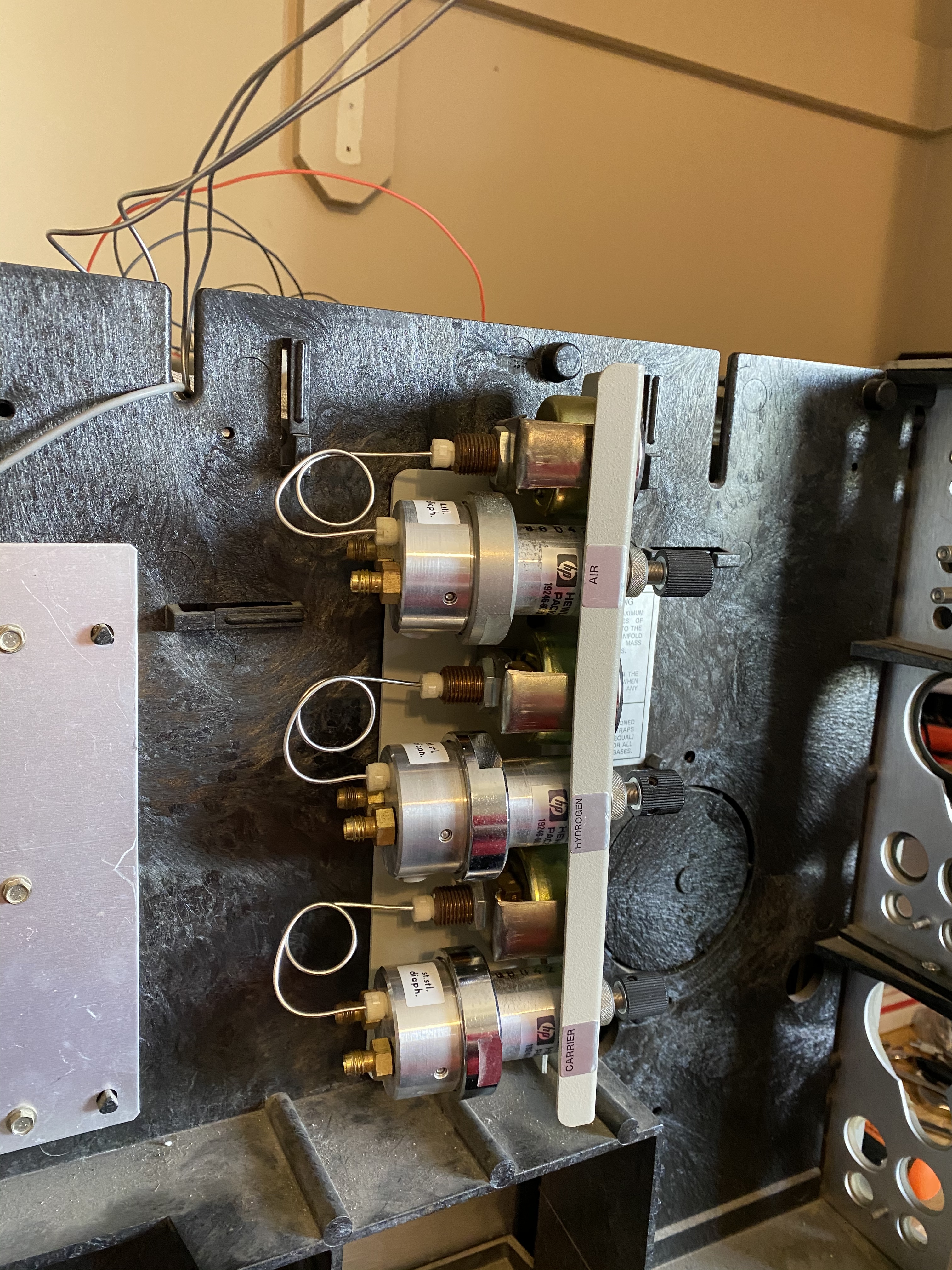
Here the regulators are added back to the manifold and the gauges reconnected. This would eventually be disconnected for hooking up the gas lines.
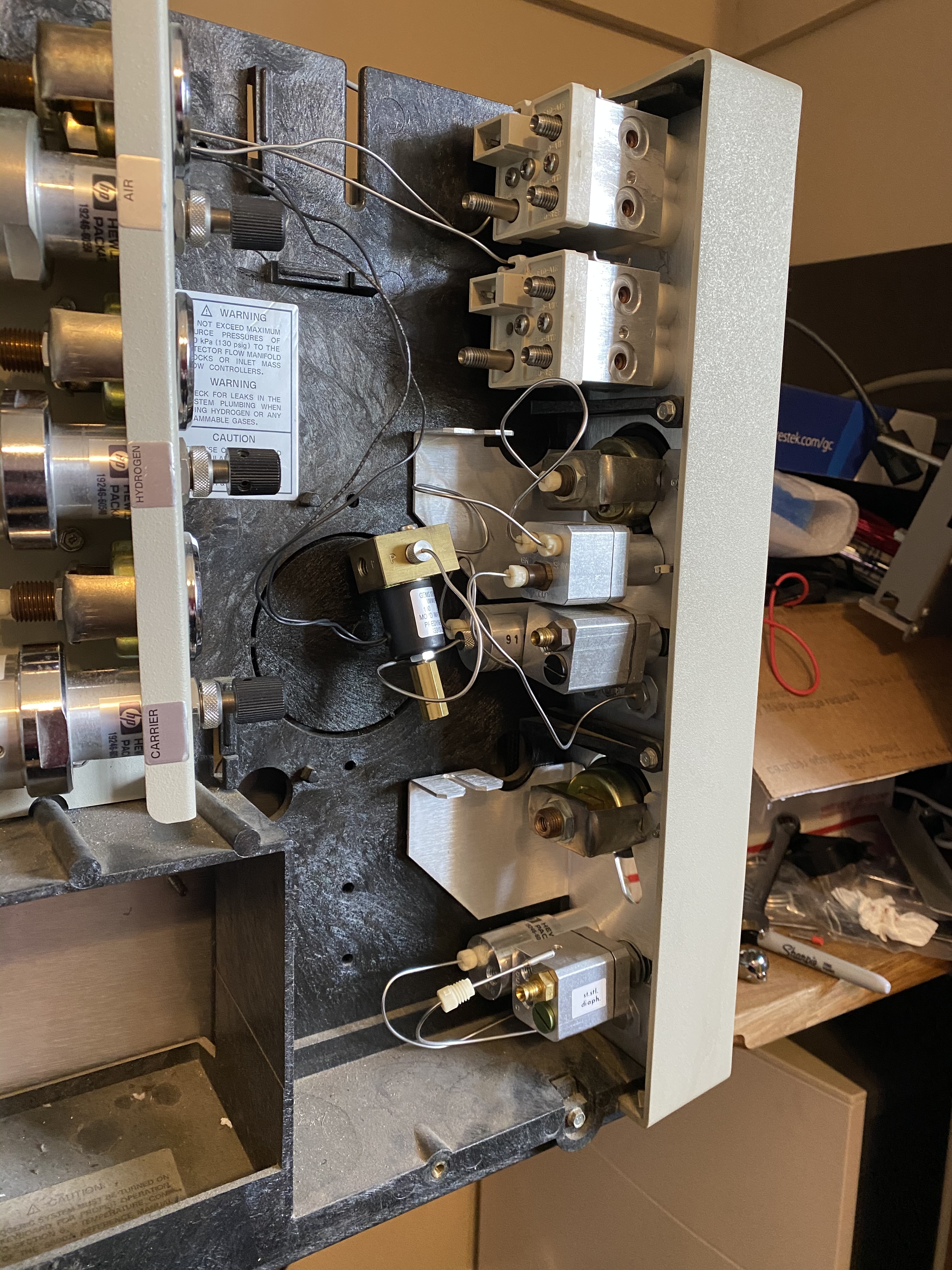
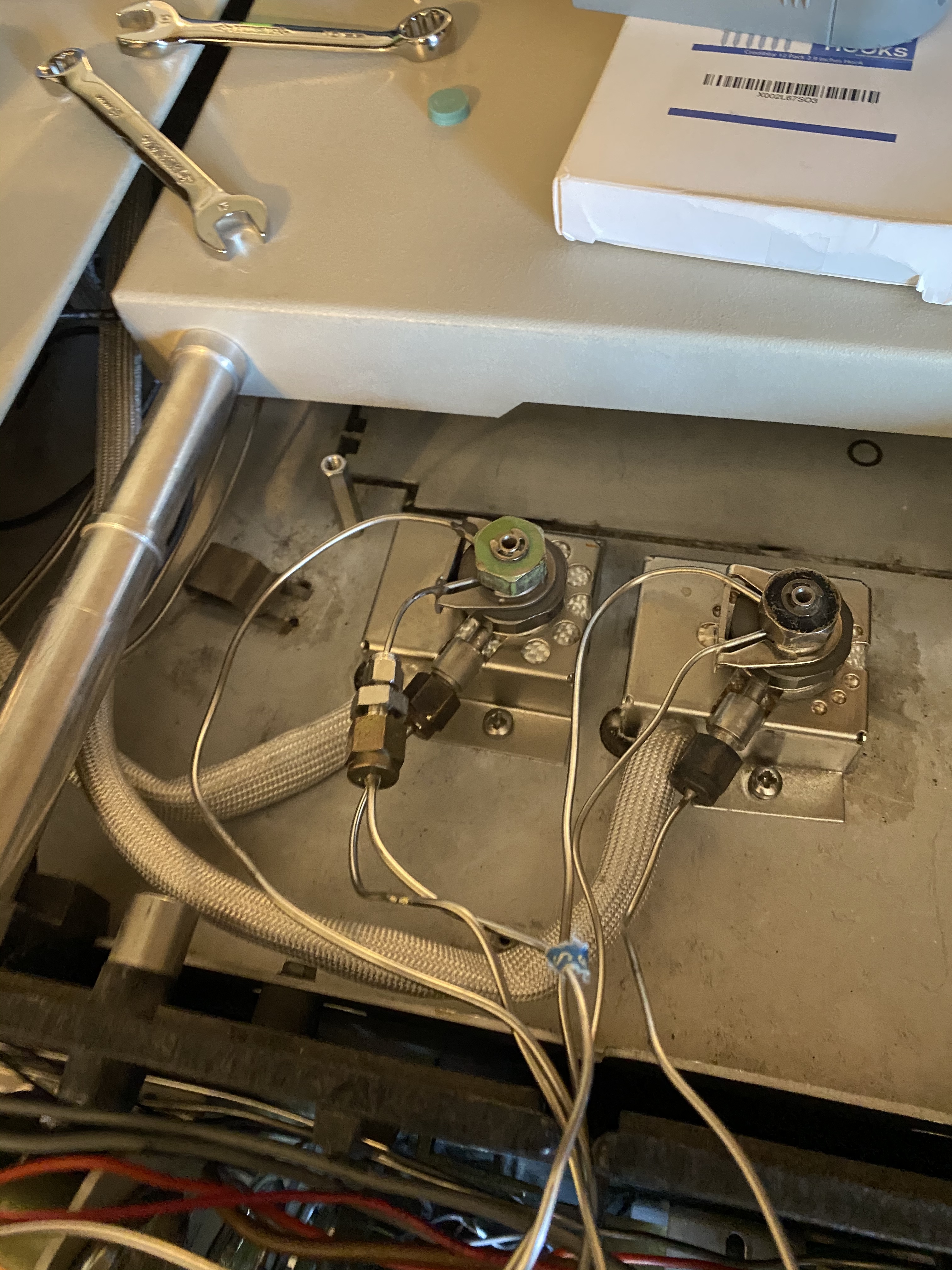
Installation of the FID flow control blocks. Added the injector A manifold and solenoid, connecting the purge ports to the solenoid to help secure it in place.
Second injector manifold (incomplete) in place.
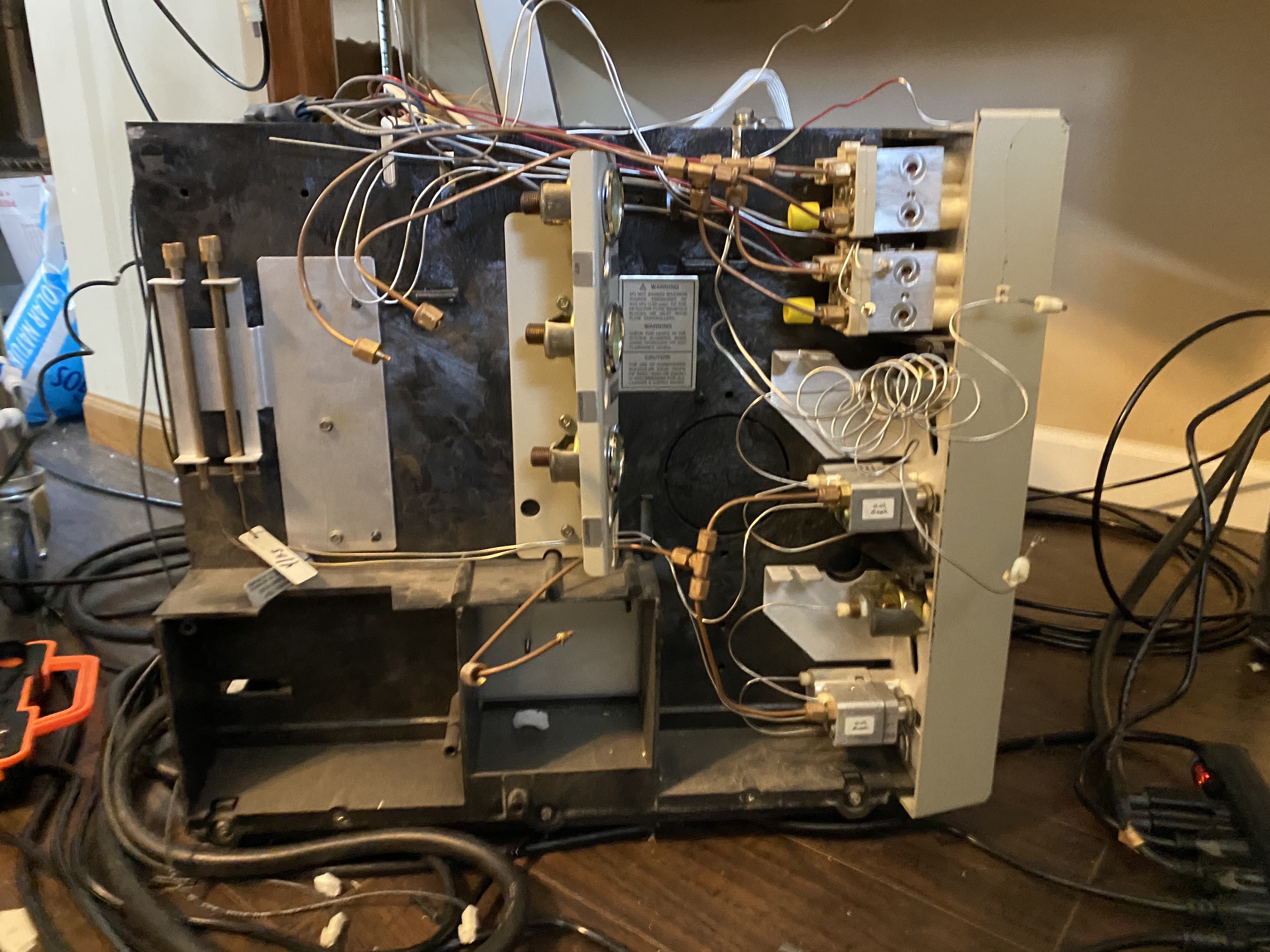
Here I have begun hooking up the gas lines. Made a few mistakes and had to re-do this only to come to a final conclusion I’ll have to replumb it anyway, as the copper I re-used was not configured for a dual port split port injector setup and my setup will require 2 additional splits off the carrier gas to the split injector purge inlets.
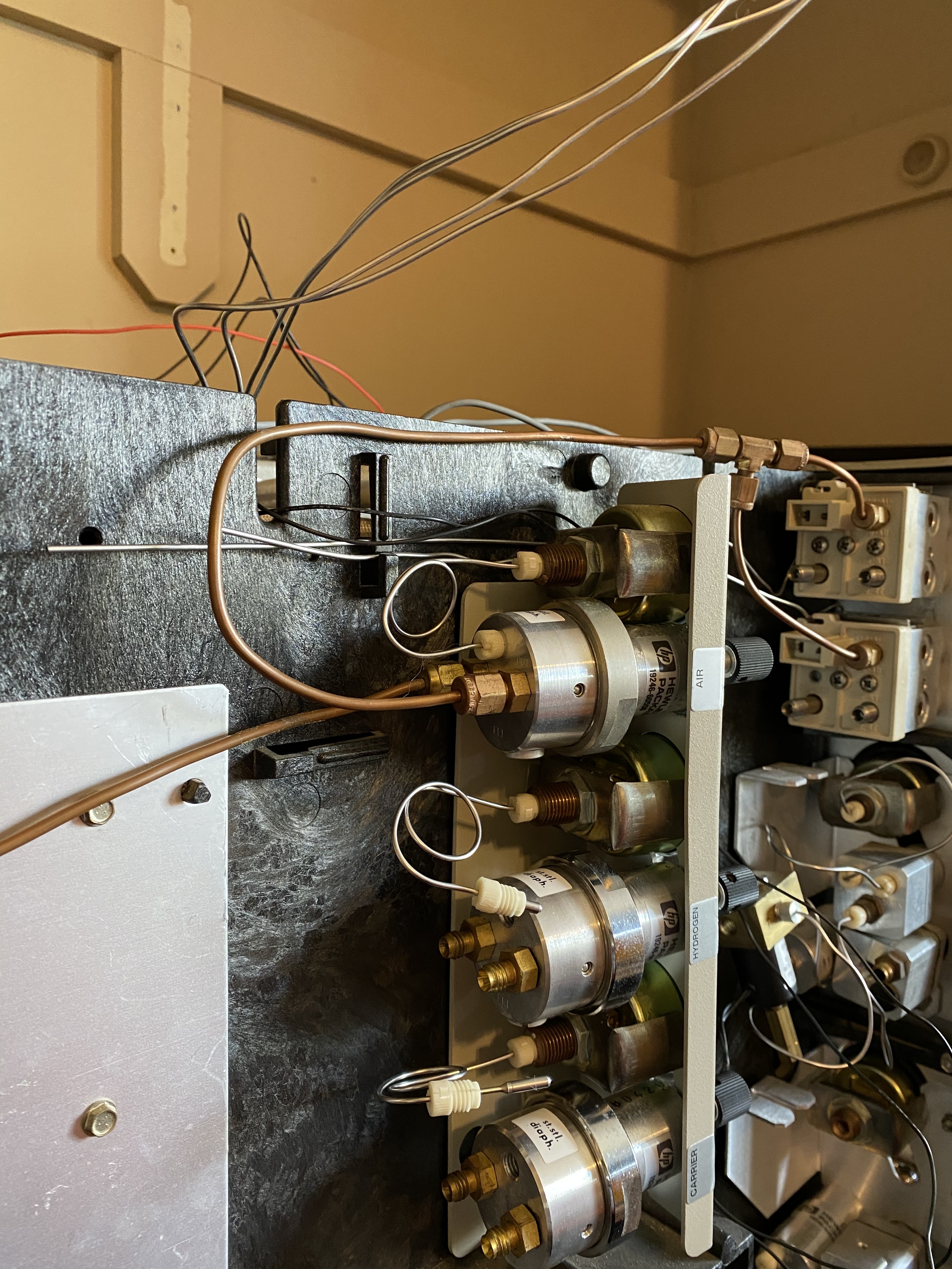
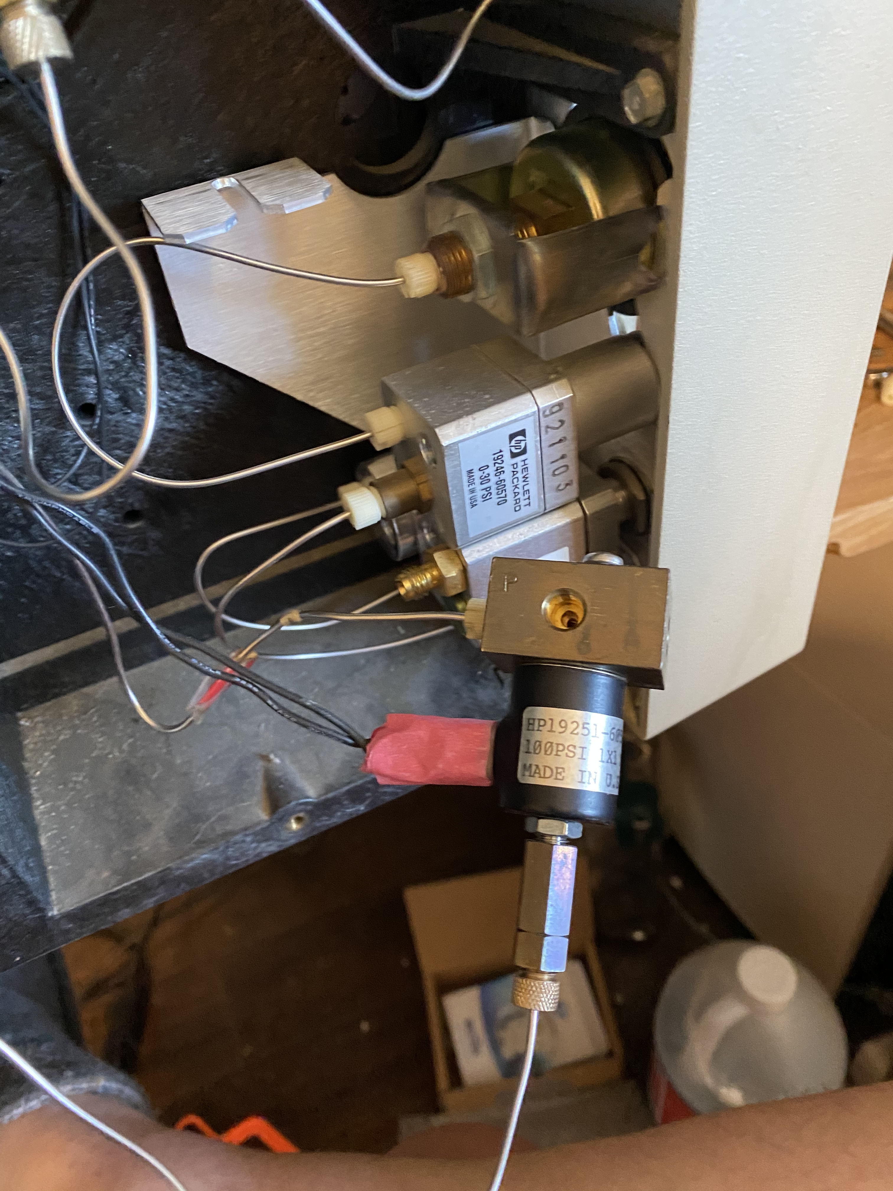
Closer view of the regulator, one line going to the back for the input and the other hooking into the flow control blocks.
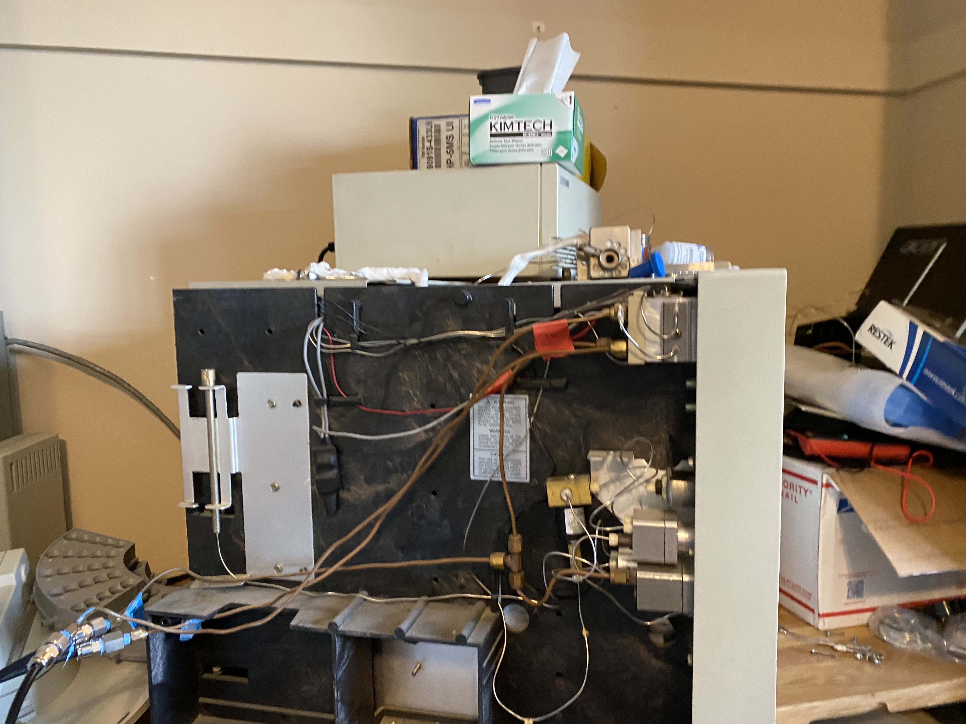
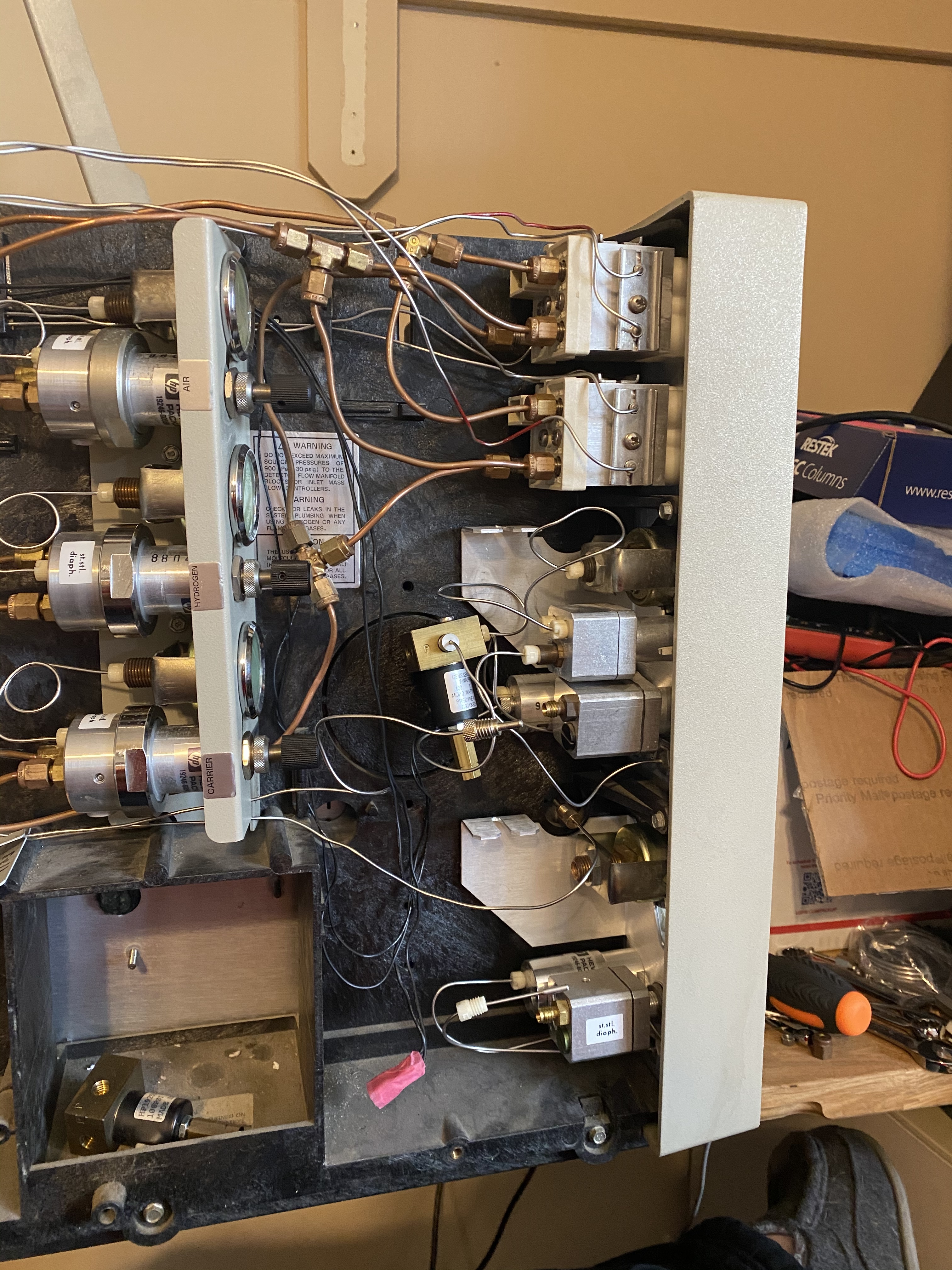
Side view with the 3 gas lines all connected (still need to split the carrier)
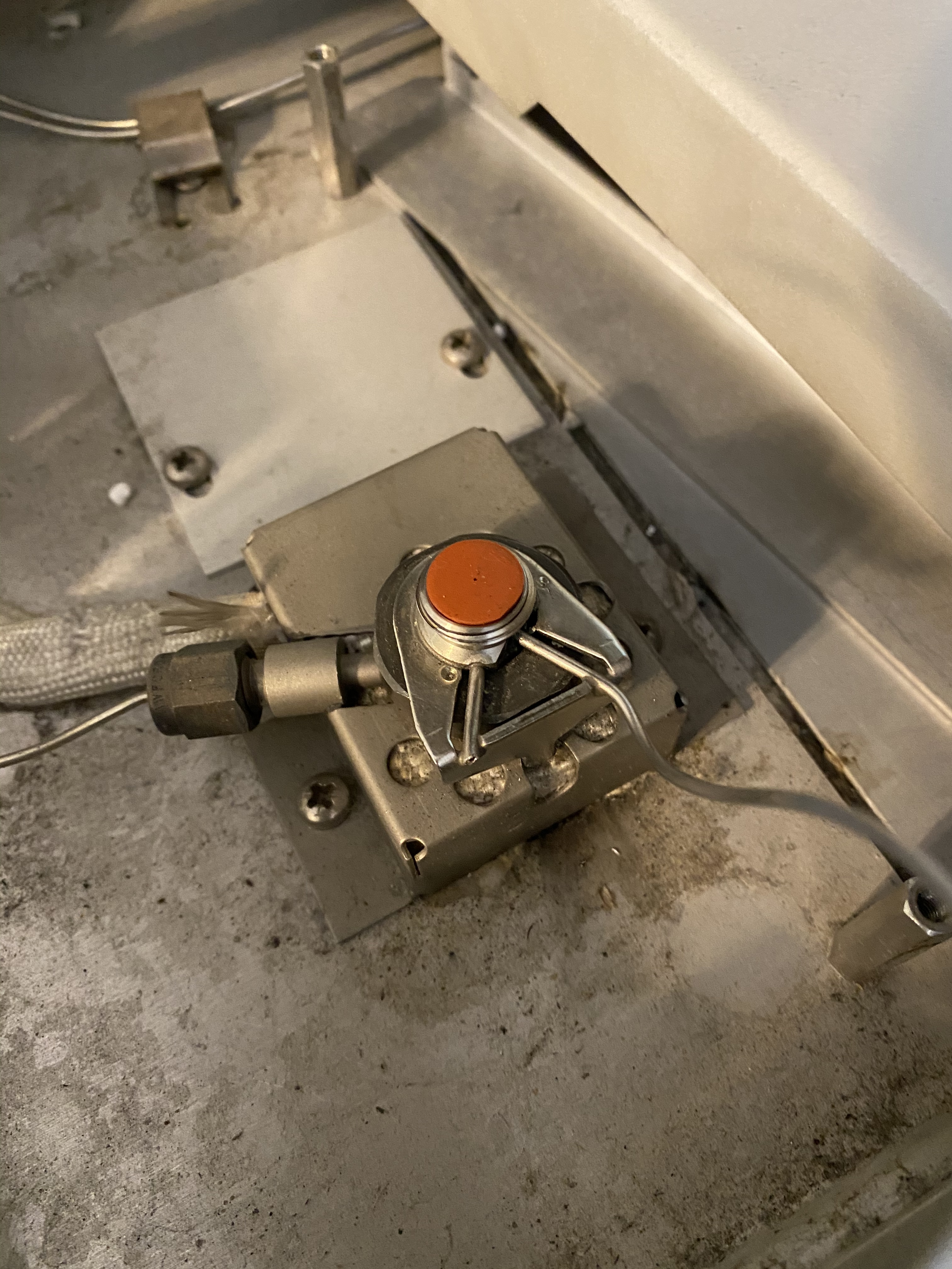
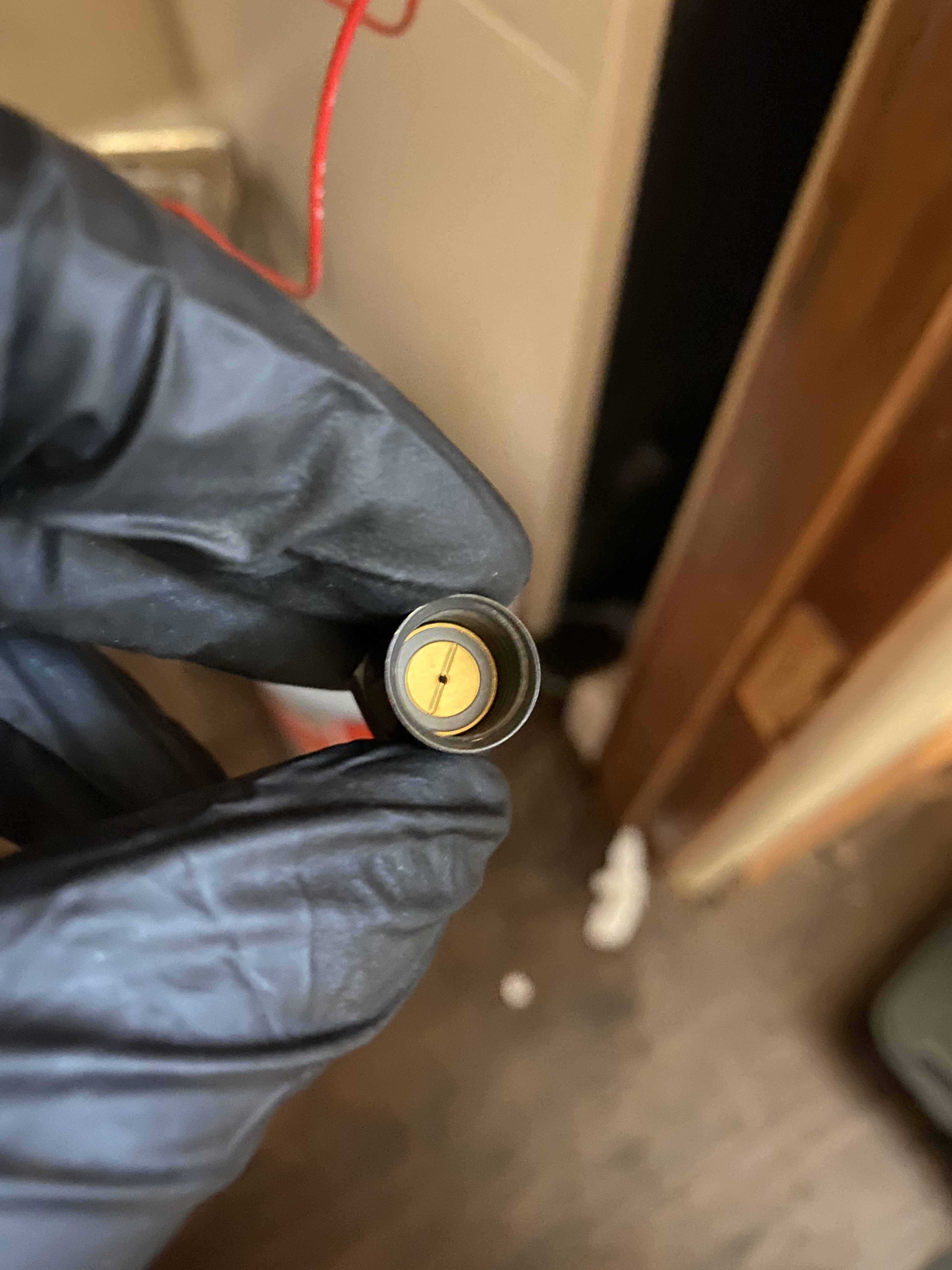
At this point, nearly 4 hours later I was running out of steam and was less diligent about taking photos. At this point I began to hookup the injector purge and carrier lines for the injectors. At this time I also decided I should do the injector maintenance that started this whole process. Here is the replacement gold seal
One of the replacement injectors, I don’t have a connector part for this, another ebay part for 1/16 compression to 1/8 compression adapter. I’ve also ordered 2 additional injectors as spares in case this happens again.
Injectors in place, Septa’s still need to be replaced, mostly this is in place to protect the new glass liners I placed in there.
What a task this has been. I am grateful for it, along the way I have learned how to somewhat successfully reterminate terminal blocks. Additionally, the Series II came with 1 FID injector; this process will give me 2 injectors and detectors so I may have the rxi-624Sil and rxi-35Sil columns without having to swap them.
Unfortunately at the end of day two I am left with just as many parts to order as I was last week. These include:
1/16 to 1/8 adapter
1/8 copper fittings, tees and tubing, ratcheting tubing cutter
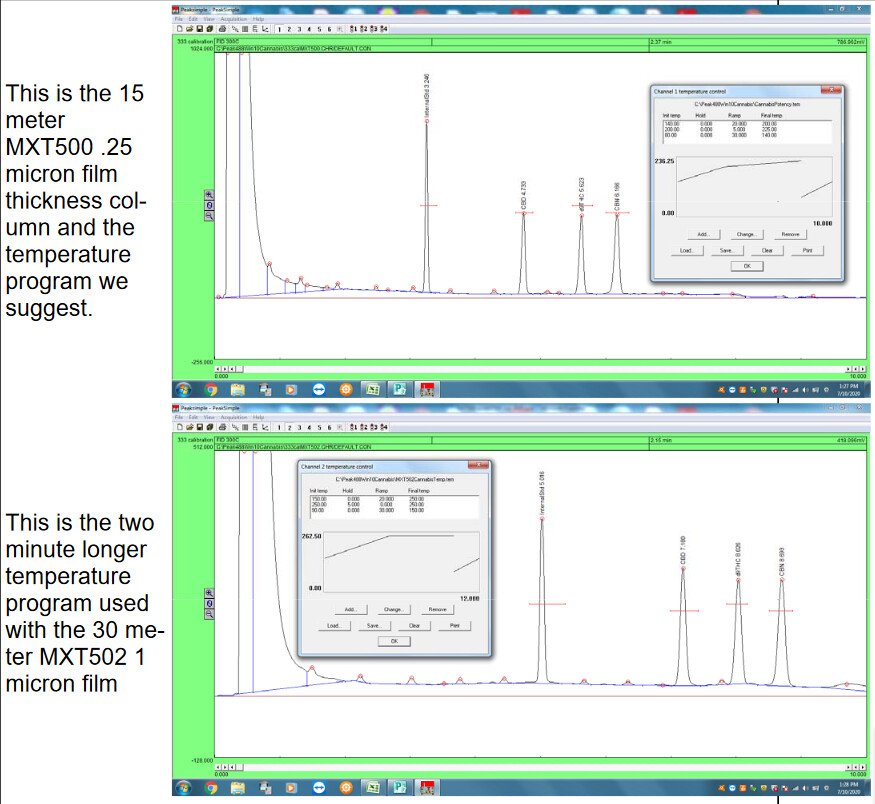
As I prepare for what will be required to run the columns, particularly looking at the chromatographs provided by Restek I started to question, how do I reliably test the flow which lead to two more ebay purchases:
Agilent ADM2000 and a part for the flow injector to hook the ADM up to.
I’ve got two more parts in the mail I’m waiting on, a solvent caddy (not entirely sure I needed it for my setup but figured for $1 why not) and a injector insulation cover.
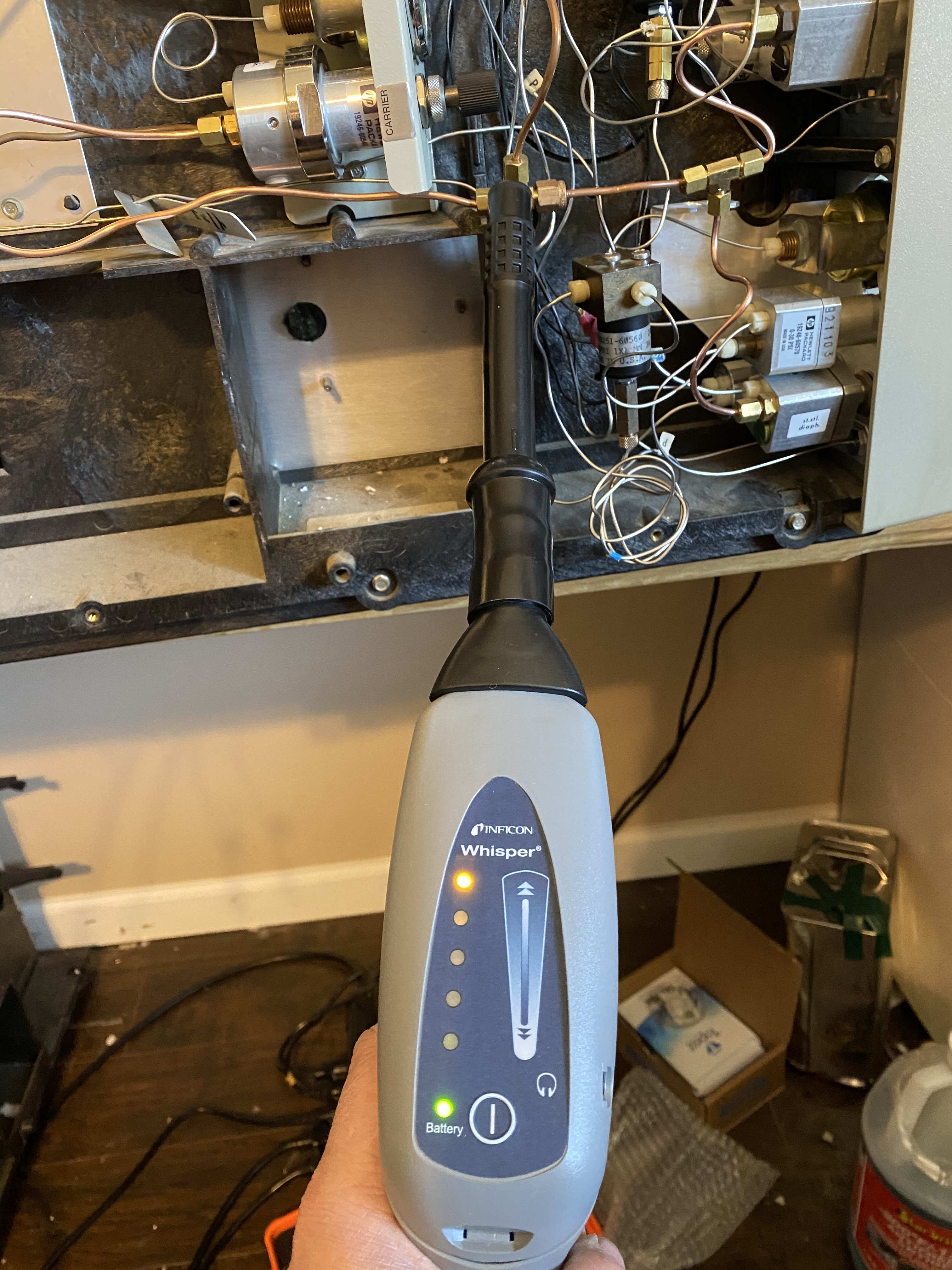
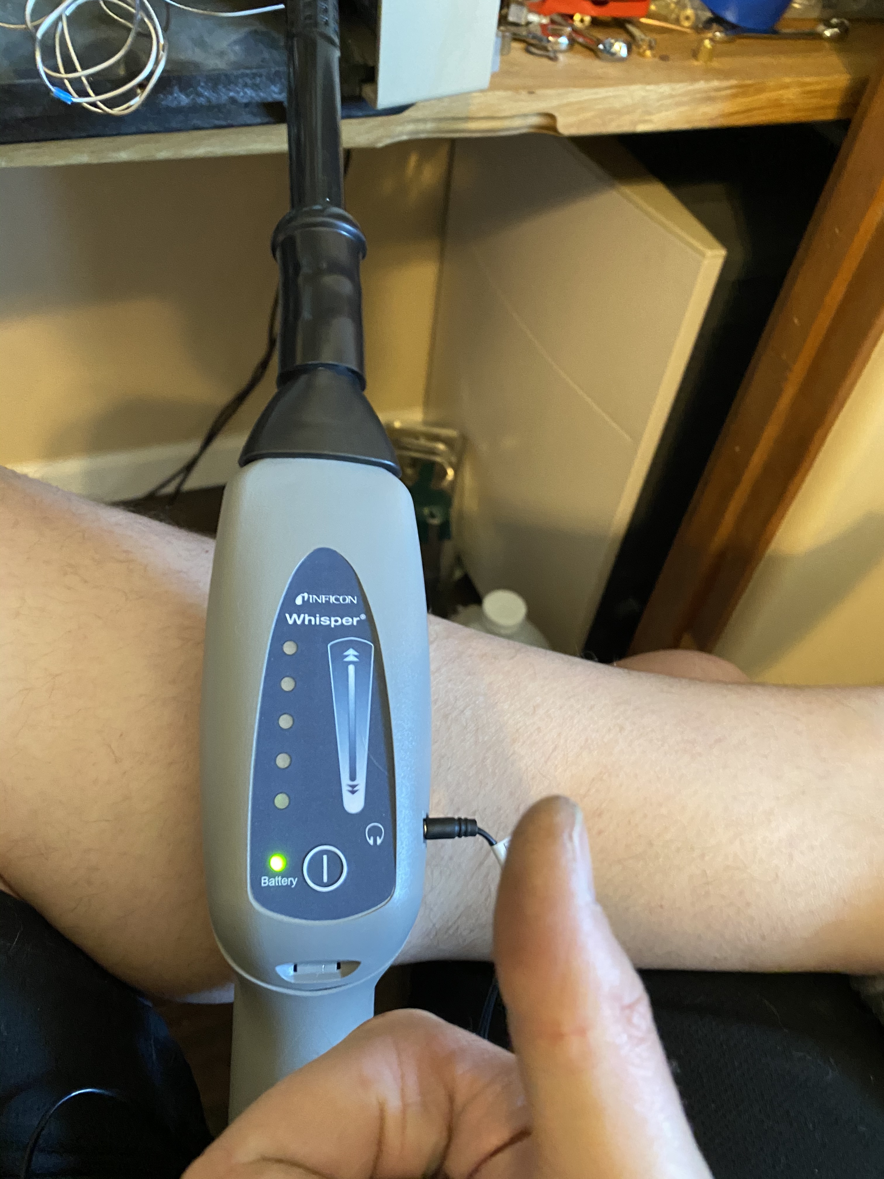
I didn’t document, but I took my ultrasonic leak detector to each of the inlets and all of the fittings. Even with improper fittings in places I was able to get leak free at 120psi from the compressor.
Still to be done:
- reinstall the injector fittings
- reinstall injector covers
- reinstall detector fittings
- replace septa on injector inlets.
- perhaps use acetone and a kemwipe to clean the injector. I’m not sure yet
- reinstall the columns. Use microscope to verify column cut meets standard. Intending to install column with 4mm above ferrule
- with everything hooked up, flush with dry nitrogen
- hook up the 4 inch duct and blower fan to exhaust heat from the GC (considering it is in my closet). I think I will get a heat barrier to tape to the drywall behind it as additional protection
- hope it all fucking works when you turn it on next