Open Source Pre-Roll Packer

Hello Future peeps. I’ve been a member of this forum for about a year and reading for about 2. For the last 1.5 years, I’ve been slowly adding, modifying, and adding to my library of 3d printed pre-roll packer and I’m open sourcing it! I’ll start with my most current iteration, then do a bit of back-dating to show the process and the mistakes I’ve made along the way. I’ll upload all the part files, as I go and list general slicing settings (machines and filament differ a lot). Some of these are very refined designs and some are half assed as hell (you’ve been warned).

When I started, I was a synthetic chemist/material scientist with all of my work being in organic solar cells/LEDs and I had only smoked weed a handful of times. Needless to say, I didn’t know anything about this industry or cannabis in general. When I was looking for a job, I found a listing for ‘Ethanol Extraction Technician’ I decided to give it a try. I got the job and started learning and reading as much as I could since I was so inexperienced. Due to the sheer lack of information available, I had a really hard time, until I found this forum. While it all wasn’t good information, it was still unbelievably helpful. I wanted to give back to the place that taught me a lot. I didn’t have anything that was valuable, but this could be more valuable to more people.

17 Likes

Where can it be found for a test print!? Awesome.

1 Like

I’ll post them soon. Fuck it. I’m going to dump my purse rn and bring everything up to date.

3 Likes

OK. Here’s how the project got started.

Dec. 2020 ish
Some old managers bought a bunch of cordia palm leave and we had no way of packing them or even making pre-rolls for that matter. They got fired by my boss and I absorbed their jobs, but now I had to figure out how to do this shit. I had an ender 3 (cheapest functional 3d printer you can buy) and decided to design something for packing these blunts.

Because the palm leaves were stiffer, I knew they needed less support. I also wanted it to be a bit more of a modular design because we had some 5g palm leaves as well. So I decided to print it in 4 parts.

IMG_1476

From left to right, the lifting ring, the chassis, the base plate, and the frame.

The chassis was meant to be used for all kinds of pre-rolls, so I tried to make it more universal for other pre-roll sizes (spoiler alert, way too tall for anything else)

The lifting plate slots into the chassis and is where the filter tips rest when packing. It can be raised up with the lifting ring to remove the pre-rolls once finished.

Then the frame for the tubes sits on top of the chassis and the height is such that the tubes (~120mm in this case) are just below the lip. Then I put these on a vibrating table and pack from there. This was made to be modular so that 127 11mm (diameter) tubs could be slotted in.

Finally, the lifting ring can be used to push them once packing is complete. You can’t see it since its underneath, but here is a sample tube that shows it being pushed up.

I also made a packer for it since the tubes need to packed multiple times before they are done since I don’t cut them.

I do like this design and I actually still use it for 9-11mm diamter cones, but I can see a lot of my inexperience here. The height is way longer than any cone size, and the print quality is quite low because I hadn’t dialed in my slicer settings

I learned a lot about 3d-printing from it, for instance, print a singular unit (tube or cone) to make sure it’s dimensioned properly, I had a couple I printed and while I dimensioned it properly, there was a size reduction with the holes (this is common with 3d-printing) and none of the pre-rolls fit; so my 36hr print went down the shitter. Better to waste a couple test cones than run the risk of a bunk frame. I also learned a lot about support material, bed adhesion, and tolerances. Overall, it was a success, especially since I still use it, but improvements can still be made.

Here are the STL files for each part. To my knowledge, these are as up to date as they can be and do fit properly, barring some weird slicer settings. Note I don’t post them because it was a while ago.

I will also say, I use CURA as my slicer, and Onshape (the poor mans solidworks) to make the parts.

I printed with a 0.2mm layer height, which is pretty standard for my primary runs.

Lift Ring: Lift Ring.stl (759.5 KB)

Chassis: Chassis.stl (100.0 KB)

Base Plate: Base Plate.stl (3.0 MB)

Life Ring: Lift Ring.stl (759.5 KB)

Packer: Packer.stl (1.3 MB)

10 Likes

I tinkered here and there for a few months working on a 5g packer until I realized that no one in their right mind would want a 5g cigar (Makes sense why these people got fired) and I shelved it. They’re also big enough that a funnel works well enough to pack the 10 you need to make for the month lol.

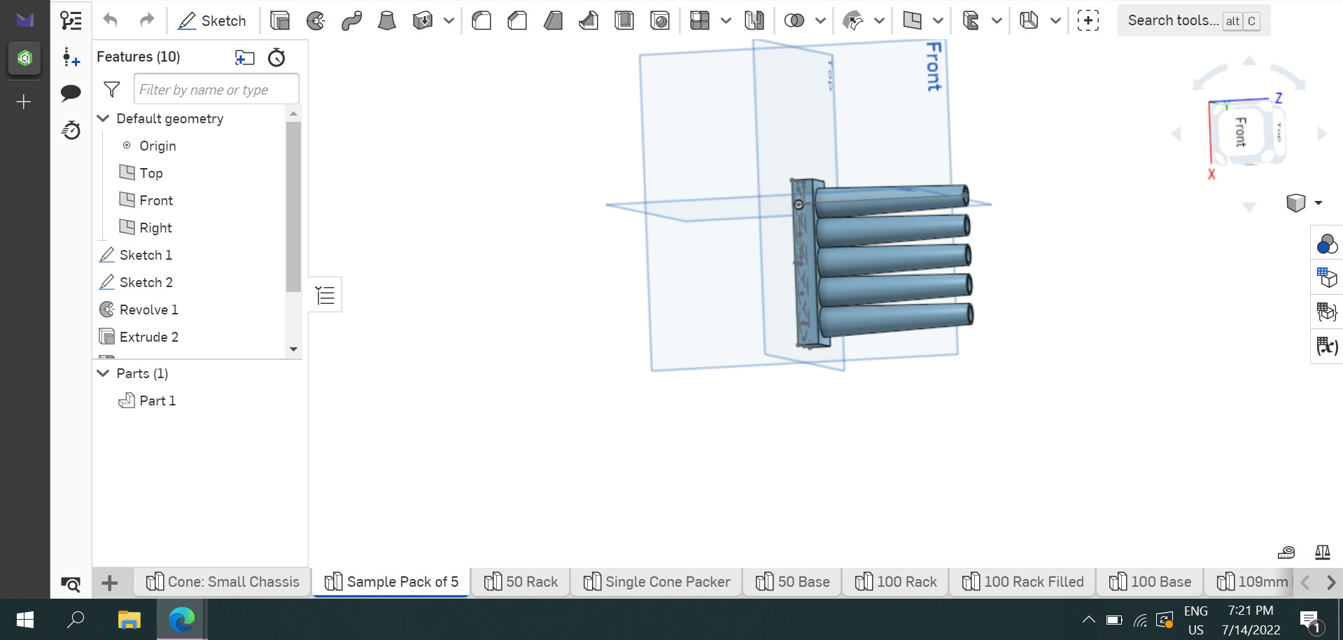
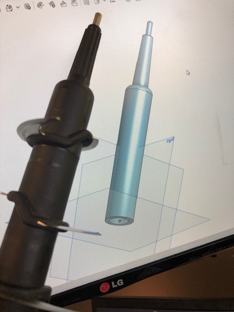
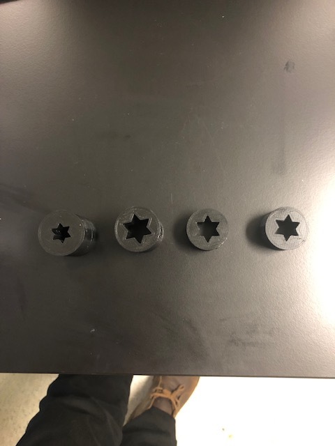
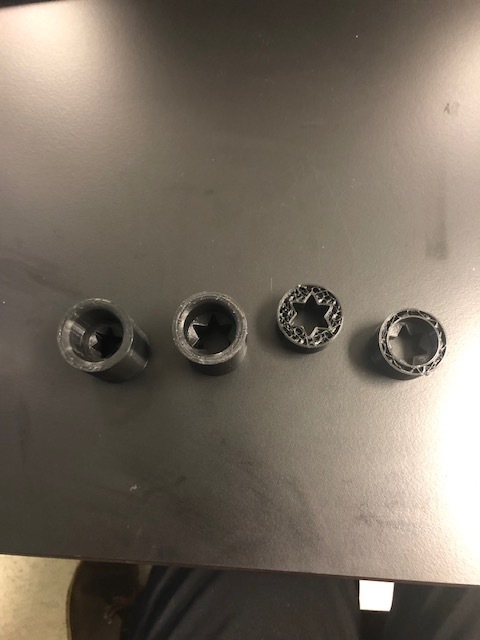
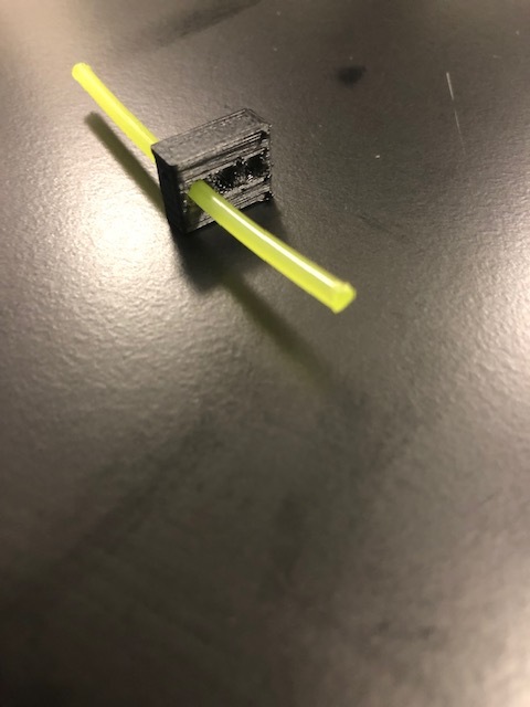
So I had the 109mm 1g standard pre-roll cone. I did a lot of thinking (and I hadn’t had any requests so there wasn’t much impetus) for me to make it that quickly. Becuase papers are much more delicate than the blunt tubes, I decided to go with a tapered cone design to support the cones as much as possible. I went through a lot of iterations before I was actually happy. Here is what a 5 packer of the thing looked like.

June 2022
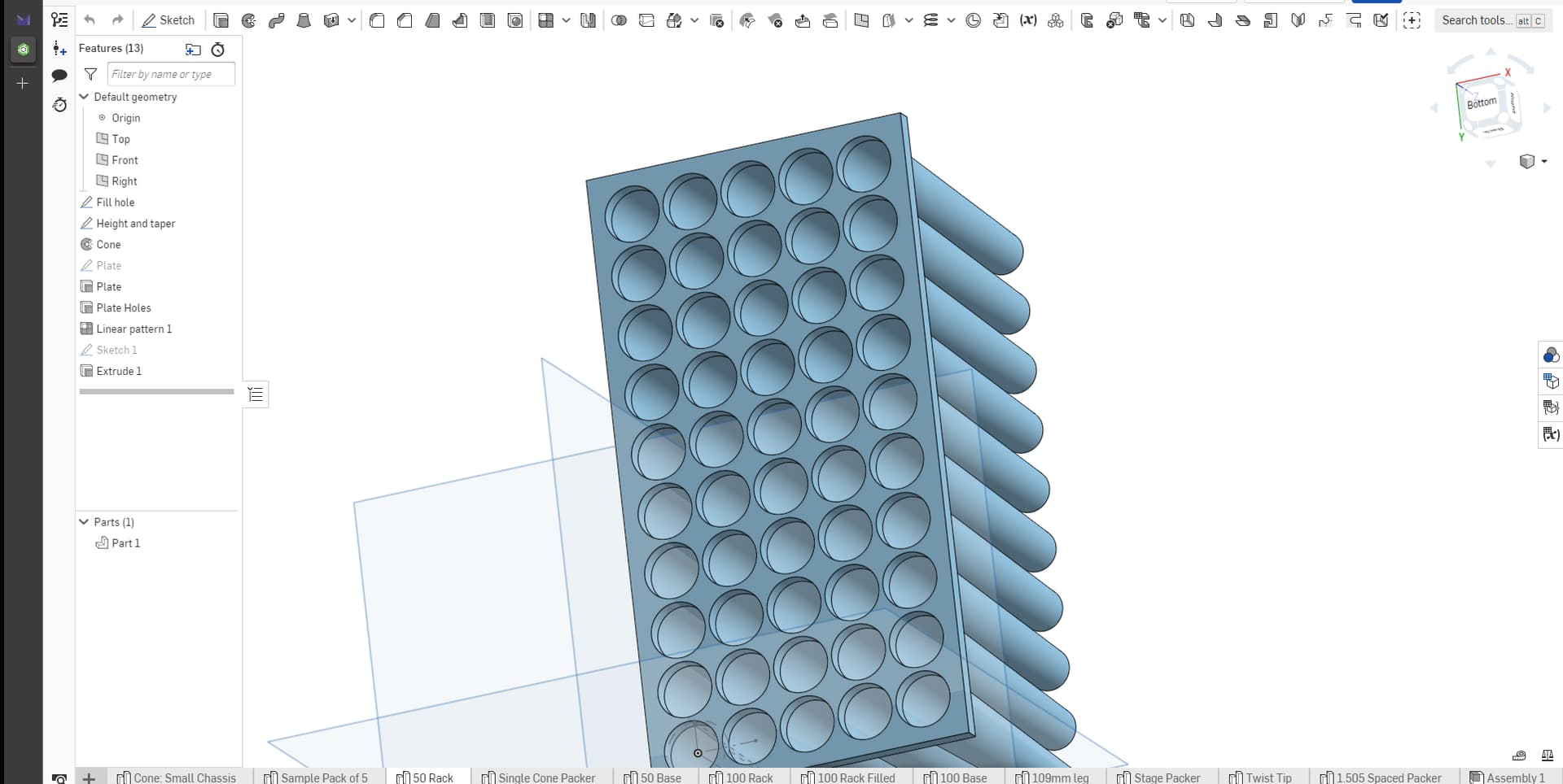
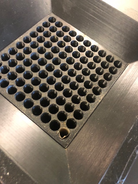
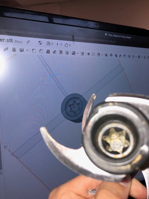
It worked ok, but I there’s kind of an issue with this style of design. All of the pre–roll filters are not perfectly circular, which makes this kind of tricky because while the diameter is about 6mm, I had to print it at 8mm to account for print bleed and the eccentricity of the tips. I found the 8mm style was better so I went for it and made a 50 packer with a small chassis/resting plate to go with it.

Here’s the 50 packer.

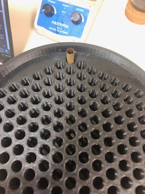
The frame for the thing, and while it looks cool. Anyone see an issue with it? The sticky little legs! It worked great, but after about 6 slams on the table, all 4 legs broke. Fortunately, the pre-rolls I was able to get out of this, were really nicely packed!

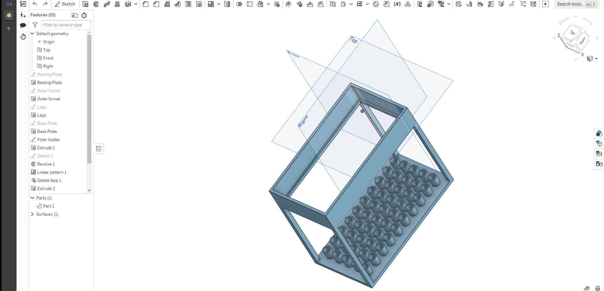
Because the packing worked well, I decided to scale it up to a 1st draft 100 rack. The tweaks I made were increasing the size of the legs from 0.5gm to 4cm, making more of a funnel shape and reducing the filter hole size a bit to make it settle better.

I also decided to try and make this one a bit more modular, so the chassis (now called the base) has removable legs and the frame slide out so it could be swapped for smaller/different size legs. I also decided to fill the frame design. It didn’t add that much print time and made it look a bit better and limited possible cleaning issues with the numerous cavities between the cones.


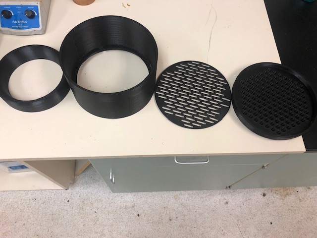
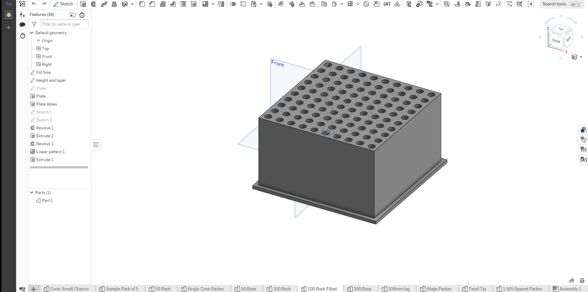
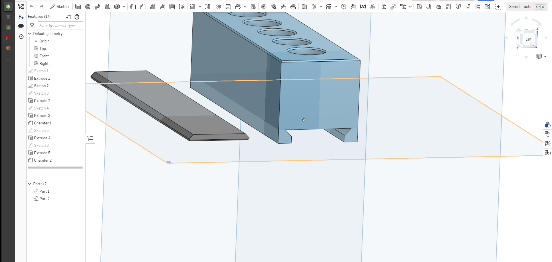
The chassis (2 day print time. Woof)


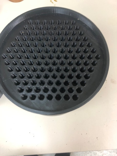
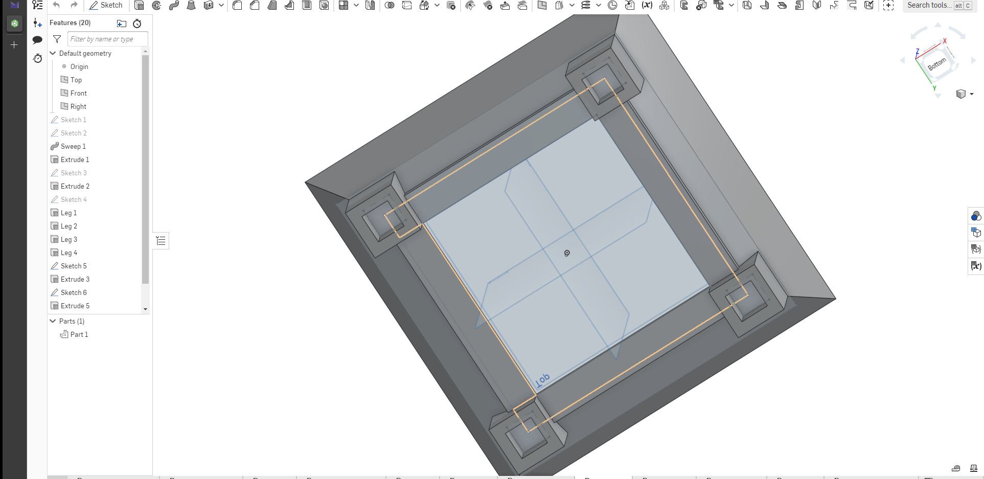
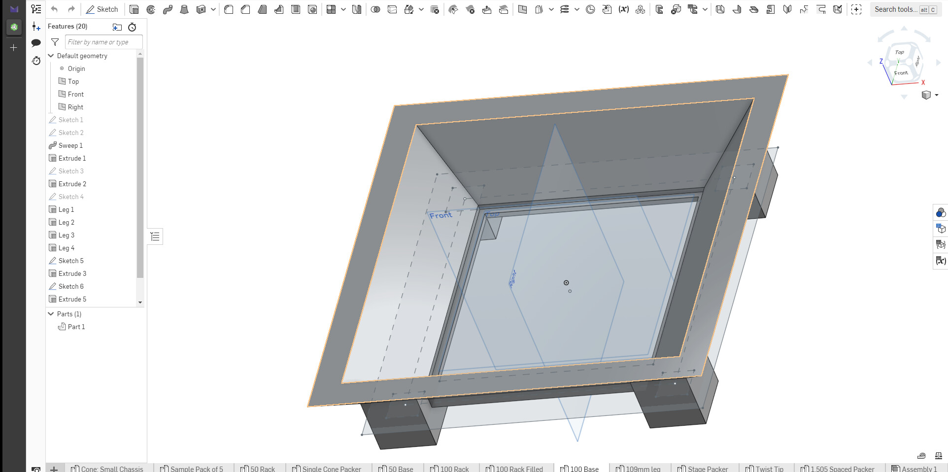
The base (top and bottom) with a nice open funnel, 4cm legs and a little lip for the edges of the frame to sit on


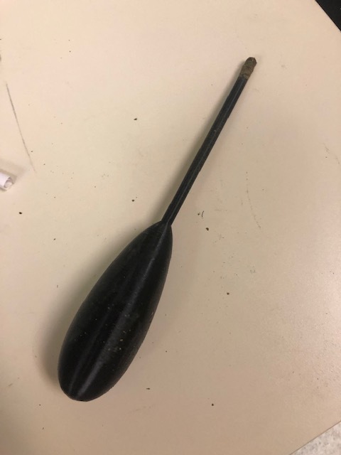
The leg design. I printed 4.

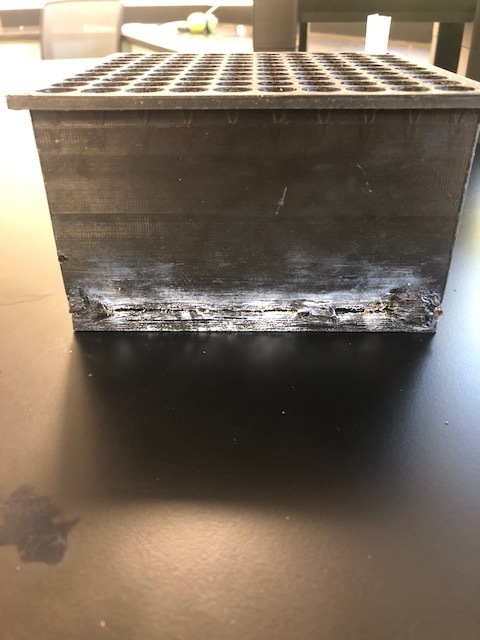
Resulting Print after ~1 week

So this was a disappointing batch. It looks like there were some issues with filament getting snagged as I got to higher layers, because there’s this wierd cracking that is going on towards the base. I tried to super-glue it together, but it didn’t help and kind of dissolve into the plastic. (I printed the top face down). I wasn’t really that happy with the surface finish on it, my BL touch (sensor for leveling the bed) was getting off because the clamp had broken so it started to mess up and didn’t leave the smoothest finish.

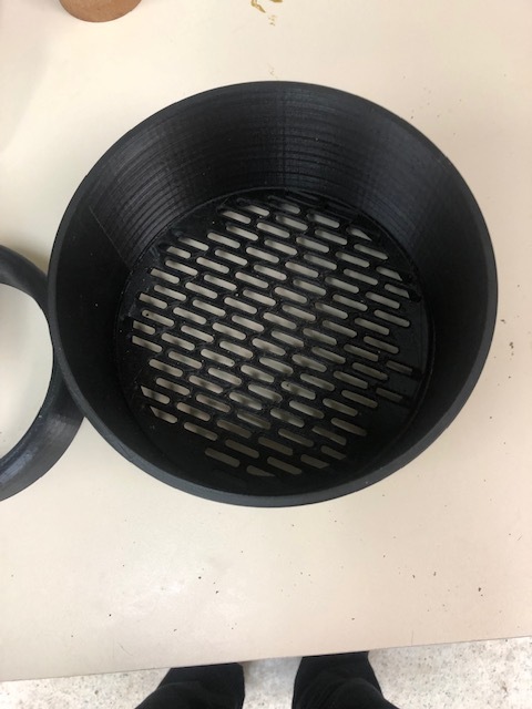
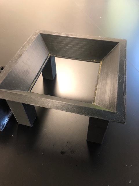
The frame came out really nicely barring a weird defect (again from my BLtouch being off). The legs also looked pretty good but fit too loosely so I had to tape them into place; had to google tolerances for pin-mating features.

The thing I really wanted to see was how did it slot into place. This was the nice thing about this design, it fit really well and the plate of the frame fit perfectly into the base.

So we gave it a try, and at first it was a fucking nightmare. I wasn’t getting pre-rolls that packed near the crutch, some were getting crinkled, and I was only able to do about 100/person*hr (really shitty). The main issue was the filters tips weren’t touching the table and thus wasn’t packing. We tried literally every packing technique we could. Packing little by little, and it really was still kinda shitty. We tried pushing them down, but it led to the issues earlier stated.

I thought I had dimensioned this thing to be 109mm perfectly, but apparently some fuckery was afoot and after reducing the leg length by 6mm and that fixed everything. I just cut the legs down a few mm with a Dremel because it was such a pain, but we diagnosed it with a few pieces of cardboard stapled together to sit under the filter tips. Now the pre rolls were able to rest against the table. When banging it against the table, it was able to hit the filter tips perfectly so they wouldn’t fly up out of the frame, but they would hit the table and pack well. Then a final pack and twist.

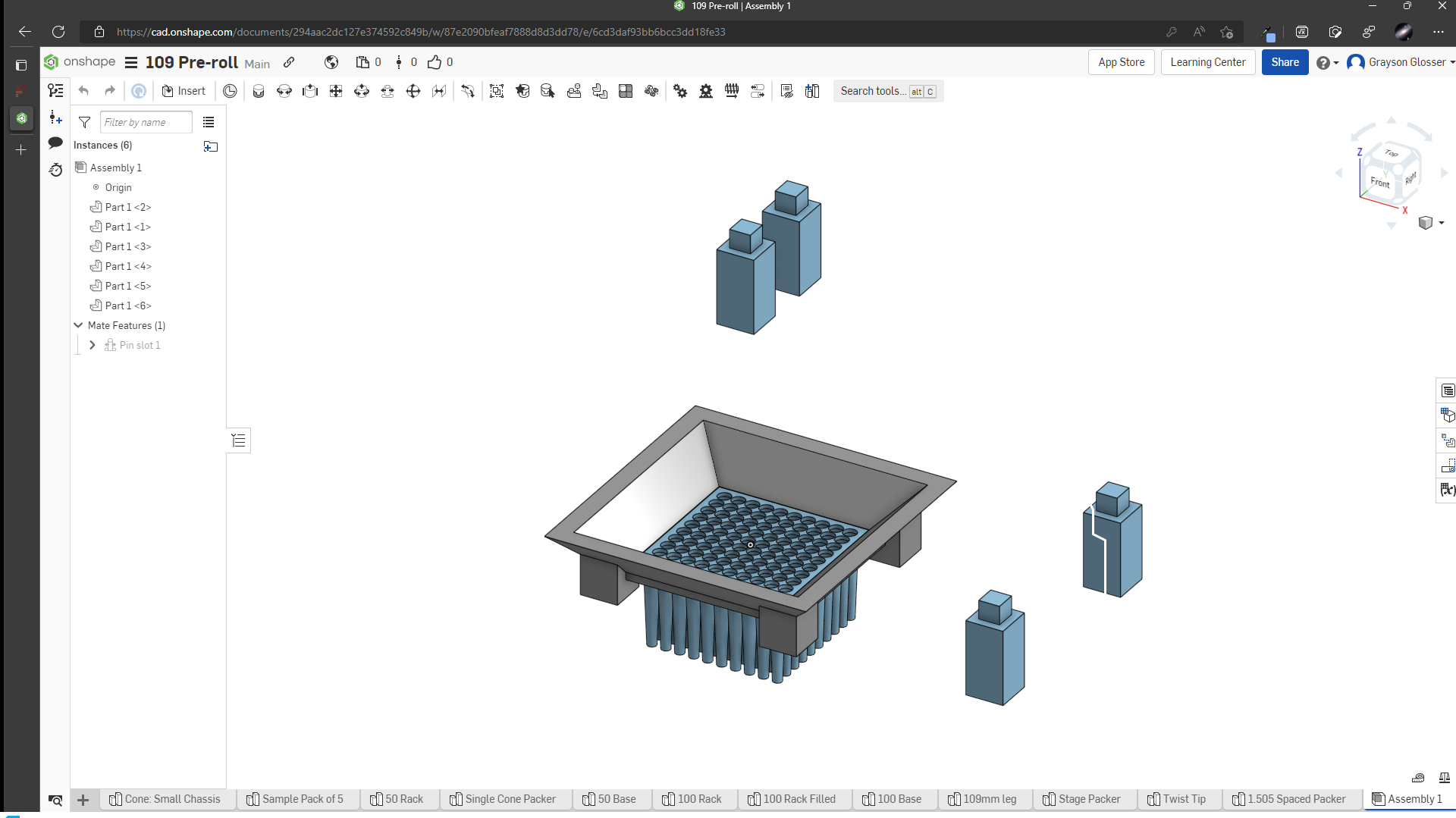
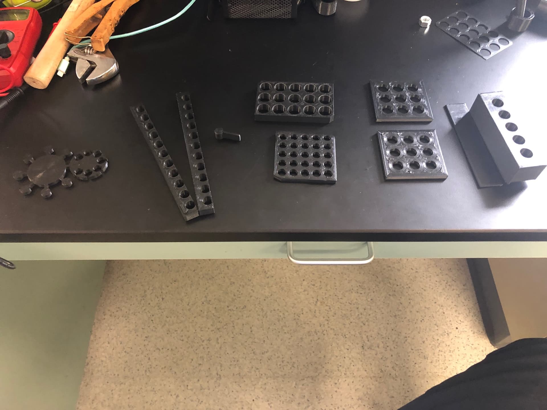
So with all that here are the parts for the most recent iteration.

Frame: 100 Rack Filled (1).stl (4.2 MB)
Base: 100 Base (1).stl (9.8 KB)
Leg (dimensioned properly): 109mm leg (1).stl (1.4 KB)
Edit: The legs are VEEERRY snug, you may need to ‘deburr’ the edges of the pegs because 3d printers tend to ooze a bit extra at right angles, its not made to be removable, but I’m not planning on removing them.

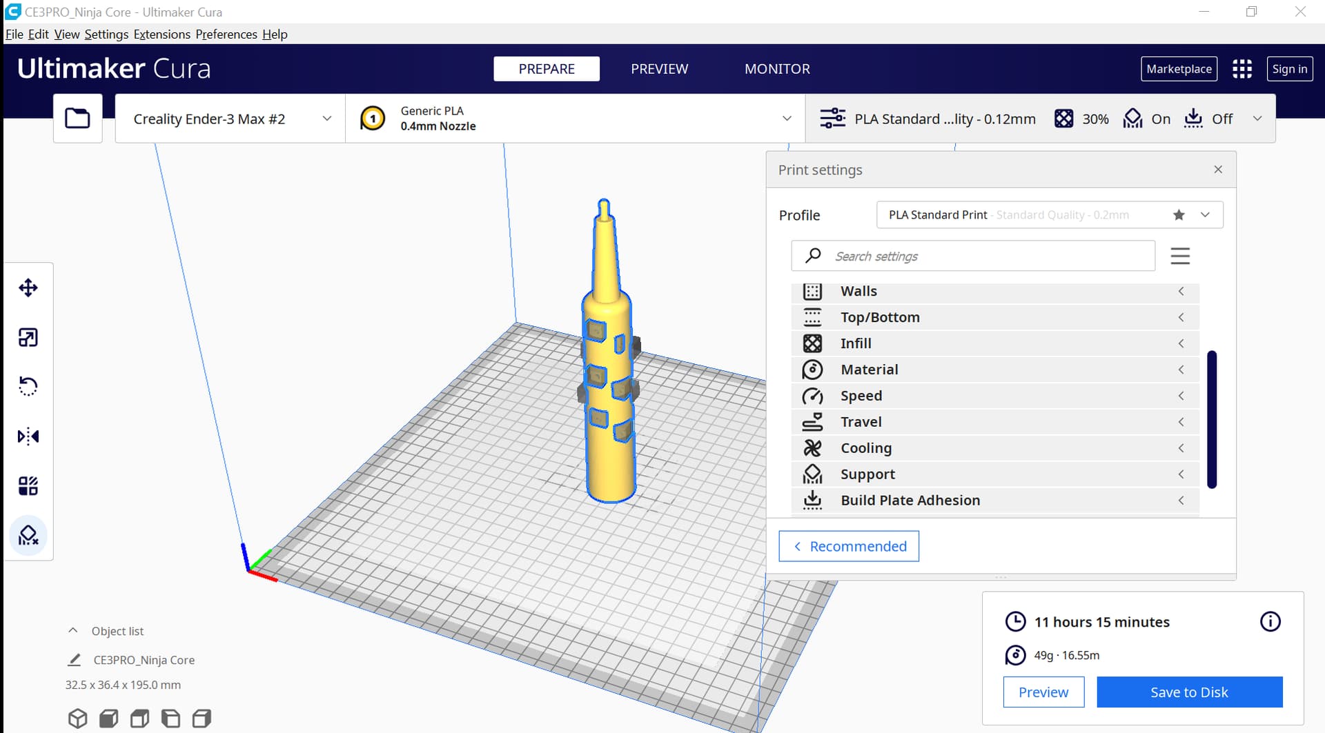
Slicer settings (CURA) for ender 3 max with BL Touch, bowden stock extruder, and glass bed. PLA ($19 from amazon).

I WILL PROBABLY NOT POST THESE AGAIN BECAUSE THERES ALOT, I’LL MENTION ANY DEVIATIONS FROM THIS IF I MAKE THEM.

Quality (can change)
Layer Height: 0.2mm
Initial Layer Height: 0.2mm
Line Width: 0.4mm

Walls
Wall thickness: 0.8mm
Wall line count: 2
Outer wall wipe distance: 0.5mm (super important to prevent stringing)
Horizontal expansion: 0mm (0.2mm is a good idea for the circles if your designs aren’t dimensioned to account for this)

Top/Bottom
Top/Bottom Thickness: 0.8mm
Top Thickness 0.8mm
Top Layers:4
Bottom Thickness: 0.8 mm
Bottom Layers: 4
Top/bottom pattern: Concentric
Bottom Pattern Initial Layer: Concentric
Enable Ironing: True
Iron Only Highest Layer: False
Ironing Pattern: Concentric (Do whatever you think is cool)
Monotonic Ironing Order: True

Infill
Infill density: (Varies) 10-15%
Infill pattern: Gyroid (super sturdy and cuts down on infill material)
Infill Overlap Percentage: 20% (Limits visual artefacts from normal 30%)

Material (PLA)
Printing Temperature: 200C
Printing Temperature Initial Layer: 205C
Build Plate Temperature: 60C

Speed (Slower walls and jerk improve print quality)
Print Speed: 80mm/s
Infill Speed: 80mm/s
Wall Speed: 40mm/s (limits blobs and zits)
Enable Jerk Control: True
Print Jerk: 8.00mm/s^2
Initial Jerk Layer: 2:0 mm/s
Initial Layer Print Jerk: 2.0 mm/s
Initial Layer Travel Jerk: 8.0 mm/s

Travel
Enable Retraction: True
Retraction Distance: 6.5mm
Retraction Speed: 25mm/s
Combing Mode: Wit Infill (Crazy important for preventing stringing)
Avoid printed Parts When Travelling: True
Avoid Supports when Travelling: True (prevents nozzle from knocking supports over)
Z hop when retracted: False (garbage setting, you will string like crazy)

Cooling
Enable Print Cooling: True
Fan speed: 100%
Regular fan Speed: 100%
Maximum fan Speed: 100%
Initial fan speed: 0%
Regular Fans speed at height: 0.6mm
Regular fan speed at layer: 4

Support (My settings aren’t as dialed in)
Overhang angle: 50deg
Support Pattern: Zig Zag

Build Plate Adhesion (Note I have auto bed leveling and it is pretty much down to the 10micron precise. Getting a good first layer is pinnacle so figure your own thing out).
Adhesion Type: Skirt
Skirt Line Count: 3
Skirt Distance: 10 mm

Mesh Fixes (Needed to limit blobs again because circles)
Maximum Resolution: 0.25mm
Maximum Travel Resolution: 0.25mm
Maximum deviation: 0.025mm

8 Likes

Coming Soon:
I’ve seen a lot of packer designs that don’t have the conical support shape because as long as you don’t do your final pack in it, it can be in an open cylinder, and it will still support is weight and pack well. My next design will take this into account, and after looking at a few designs, I think I can make something that also does the final pack and folds it into a dutch crown as well. The current speed for the above pre-roll packer is ~1,200-1,500 per person per day. Not bad for a couple kg of filament, a $300 printer, and a free solidworks. If I can pull off this next design, I estimate I can get between 5,000 and 7,000 pre-roller per person per day, all while having a perfect pack.

Another facet I want to set up but have zero time for is doing a study with this stuff. I’d like to measure burn time, ember lifetime, etc. against the packing stiffness, grind quality and sift blend. This will have to wait though because I at least know how to make a decent pre-roll now!

6 Likes

I don’t speak for all but this is incredibly detailed. Thank you. MoM worthy

3 Likes

I’ve been wanting to make something with adjustable speed and stroke, vibrating table is an interesting idea as well

Thanks for sharing!

3 Likes

@moveweight thank you very much, though not quite MoM worthy yet. I still have a iterations before this thing is perfected.

@pdxcanna That would be really interesting too. The vibrating table I have is more of a horizontal action, not vertical so that’s why I have to slam it on the table (more fun to me). Seems like it would be easy to wire up though, just a variable resistor for speed and a way to change how compressed a spring gets or how much the frame rattles.

3 Likes

Pre-roll packing is one thing, but proper material prep is equally if not more important. This is the grinding and sifting of flower. I currently use a ninja blender and pulse it in quick bursts then sift it through size 12 mesh. Many pre-roll purists/snobs will tell you a ninja is unacceptable, and you should kill yourself if you even think of using one, and that you need to get specific with the mesh sizes, using blends of size 12 and 14 mesh to get the perfect burn with a fine mesh to remove unwanted kief/fines.

I can tell you personally, ninja blenders do a good job in most cases. They make a good pre-roll, smokes well and it mostly comes down to your packing technique. As long as you aren’t over-grinding flower, you can’t really go wrong.

HOWEVER, there are some cases where I wish I had either a high torque grinder (see custom cones) or something similar to a Futurola grinder. I would argue a high torque grinder is better in general because how low speed it is, and I’d like to fabricate something similar soon, but Futurola grinders seem to be almost an industry standard and produce very nice results (correct me if I’m wrong). Unfortunately, they start at around $2,000-$3,000 for their smallest sizes, which really sucks.

But upon looking at what a futurola grinder is, it’s very similar to a blender except with stiff nylon whips. So why not just 3D-Print a rotor shaft that can take bristles and uses that instead of blades?

I’m starting by just dimensioning the actual shaft itself, I and will dimension it for the line later. While I’d like to use futurola’s nylon whips, they’re $50 for a replacement set; a bit overpriced if you ask me and I don’t want to wait a week. I’m going to try the line I have from sunjoe leaf mulcher. It’s very stiff, and should hold up ok as long as they are cut to length.

For now, I’m going to do a test print of the tolerance of the star shaft since the tolerance on that is the make or break here. Feel free to chip in with better/more widely available whip material/sources so when I drop the final part, yall can go and make it.

2 Likes

Ran some test prints to make sure the tolerance between the shaft and blade core were dimensioned properly. Glad I did because I was way off. Once I got on point, I had to reduce the size 2 more times to make it have a snug-sliding fit. Hard to get a set of calipers into a blender :man_shrugging:.


I want to stress the importance of test prints, these each took ~30min a piece and weighed ~6g, the full print is 3.5 hr and is 30g. Using 20% the plastic is hella useful. I also stopped the last 2 a bit over halfway because they were done enough. This let me iterate this over the morning while doing paperwork tasks. This is also a modest case, and 25g can add up if you print enough, but ruined parts can ruin parts that weigh over 100g; I know because I’ve done it!

The next step was doing tolerance tests for the holes the whips would take. I was considering doing a semicircular design where it would come in and go back out, but it would be really hard to dimension to tell if there was any blockage and I’m not that good at solidworks.

I also tested to see if I needed support material for the holes or not, and it looks there isn’t any need for it. This is good because support can be tricky to remove and maintain tolerance, especially from small features. I do wish I had a dual extrusion mechanism so I could print soluble infill for flawless surface finishes and tolerance on all faces/print orientations, but it’s not a huge deal; perhaps a good future project/purchase as it would be a hard conversion.

While it is a bit loose, I think that is just by function of it being a 1mm thick test piece, when it has to go through the whole body, I think it’ll be fine. So now we’ll get the holes dimensioned on here.

3 Likes

Ok, all sliced and ready to go. I was planning on doing PETG, but after seeing the glass transition was only 20C higher (80C instead of 60), I figured PLA would be fine. My PETG settings aren’t nearly as defined as my PLA.

Not too bad. Here are the specific print settings I changed for this model:
Quality: 0.12mm
Initial Layer Height: 0.12mm
Wall Line Count: 3
Infill: 30%
Support Desity: 5% (PERMANET CHANGE)
Support Overhang Angle: 65 deg (the reason I did this is because I don’t like as much infill on fillets, small ones are especially susceptible to poor surface finish with support material. Increasing this number works for this model because the places that really need the support are 90deg overhangs and won’t be affected, it may not work for all models and can cause some prints to look shitty!)

4 Likes

man bro, this is perfect. ill be following this and printing along.

1 Like

I’m printing now. if there is anything you need help experimenting let me know.

1 Like

6o hours 24 mins nd 34 secs at 99% for the base. your print settings were perfect. no stringing what so ever.

2 Likes

Been a few weeks, the Mk III is in progress, and I’ve been doing a tolerance tests to make sure things are functioning the way I want. Always glad I do this because I ran into a few snags along the way. I tried to test the sliding tolerance and I noticed what’s called an elephant’s foot effect (first 5 pieces on the left).


Basically, the first layer is too close to the build plate and the plastic is squished out in the xy direction leading to a wider than planned. This is a big problem because my holes will not be the same diameter all the way through. I tried messing around with first layer flow, raising the bed, printing with a raft but that led to prints coming off and poor surface finish. I found the best way to mitigate this is with an underside chamfer of 0.5mm. This lets me get good bed adhesion while eliminating this issue.

The other ones are testing the diameter by stepping down by 0.5mm at a time to really dial in the diameter. Still working on it, but 1.3-1.35cm seems to be optimal for 109mm cone. Also making a lower diameter plate for support while packing.

The print all the way to the right was a dosing plate where you fill it then put it over top of the cones and slide the plate off to fill. I was testing the sliding mechanism but I had the edges a 90degrees, which meant I needed support material, but the slot was too small for me to get it out (cut my hand with a fucking flat head screwdriver like always). I modified the design to be at 45 deg so I didn’t need support material. You can also see the underside chamfers on the model.

See you in a few weeks.

9 Likes

DUDE! Awesome work man! One thing I might suggest if you haven’t considered it yet is acetone vapor smoothing for ABS plastic. I know the layer lines and elephant’s foot causes tolerance and sliding issues. If you were to print in ABS and then basically put it in a rack inside of a crockpot of acetone such that the part is out of the acetone, the vapors will etch the part and leave a super smooth finish that may slide easier without catching on the layer lines. Of course by eating away at it, it will change the tolerances of the part but using the same process each time and modifying the tolerances to fit would probably control for that. I would also think that the smoother parts would be less prone to sanding each other down which could potentially deposit plastic into whatever is going into your parts. Either way, awesome work man!

9 Likes

I do know about ABS smoothing, I actually haven’t worked with ABS, though I have considered it to be able to smooth it. There’s a couple reasons I don’t like ABS.

I work with pla mainly because the off-gassing is reasonably non-toxic whereas ABS is likely less safe. The overall increased biocompatibility of PLA makes it my go to for production parts, barring PETG for solvent-contact. I know PETG has phthalates, so I do hot soaks in ethanol to remove what I can.

I’m considering doing a small amount of sanding to do this, though a small amount of part abrasion is ok in this case. The plate design should make cleaning easier to and limit how much gets stuck on the layer lines. Plus it doesn’t need as much force to pack properly so it should limit or eliminate the amount of plastic that gets into the pre-rolls. This is why I avoided using a raft/support material for a smooth surface finish (glass bed on bottom, ironing on top).

The smoothing wouldn’t really fix the elephants foot, since its an expansion on the first layer, not a layer line issue. Additionally, ABS is much more subject to warping (I think) and I don’t have a heated chamber so my failure rate might be higher. I’ll consider it if it’s still a problem but I’m already having to do a LOT of testing and changing filament would break me.

Appreciate the suggestion though and that owl looks hella fly.

With finely pieces like that owl, you get a lot of defects from the rapid changes in direction (eyes and feathers) so the smoothing really helps remove those defects.

2 Likes

Completely understand where you’re coming from. I have always wanted to play with ABS and vapor smoothing but haven’t simply for the reasons you mentioned about HCN off-gas and it’s temperature gradient sensitivity. That being said, one of these days I’m gonna try my hand at ABS parts at min infill and vapor smoothing because I would love to play with lost ABS casting. I’ve seen some really kickass parts come out of that method and I feel like it will really bridge the gap between 3d printing in plastic and metal without the crazy high associated costs.

1 Like

I meant monomer (styrene, butadiene or acrylonitrile), does it off gas HCN?

1 Like