I can nay get the power Captain!

I’m with you. Having voltage on the high side is better. I do like to keep everything withing 5% of nominal though. To be honest I wouldn’t even recommend changing the taps on the transformer with out knowing if there is a primary side low volt issue. Primary tap changes are not meant to correct secondary low volt issues likely caused by voltage drop.

Nah. That confusion is my fault. Motor wants three phase. VFD in box insists on single phase.

I had not opened the box when I posited that the chiller frying one pin on its plug, a centrifuge throwing “low voltage errors”, and a “we’ve finished with the new circuits” within 24hrs looked like something I should poke harder at.

Power company is supplying 203V at the 2500A disconnect.

1 Like

203V measured on the incoming side of our 2500A disconnect. Next cabinet over has power company stamp.

1 Like

The emerald city…

2 Likes

That’s good to know you don’t have much drop across your system. Hopefully the utility will be able to help you out but maybe they wont.

I think this might be important. in fact I’m almost sure it is…

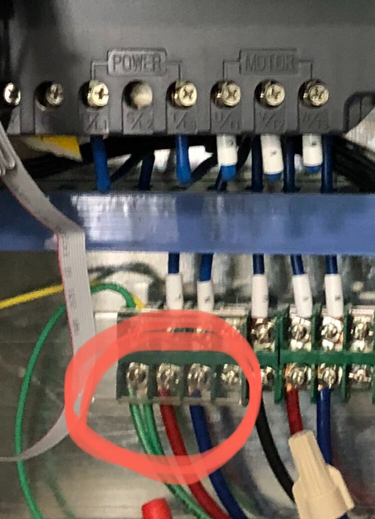
I’ve got 202V between red and blue and 116V between either of them and ground. if those two 116V’s were 180o apart, I should have 232V between them. No?

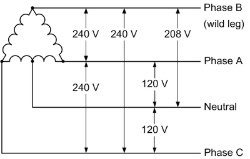
the only way I can see to have 202V (208) between them would be if they were (120o) out of phase…(which we expect in a 3-phase installation)

image

it’s pretty clear from the fine manual, and the wad of glue in the S/L2 terminal on the VFD that this thing wants single phase 220V. they’ve been running for a couple of years on whatever they’re bing fed, but they’re clearly not super happy with the concept, and I’d like to solve that…

edit: …and this video 120V from both 240V single phase and 208V 3 phase systems? - YouTube suggests that I’m either gonna have to throw a transformer at the problem, or tell them to suck up and deal…

edit: given the amount of pissed off Chinese equipment there is around here, I’m not sure the transformer option isn’t a good one. (what I really need to do is get all our solvent recovery moved over to membranes)

1 Like

Yes thats an interesting point, I had assumed they were out 120 degrees based on those voltages. Maybe worth having one of the electricky people break out an oscilloscope to see if something is badly fucked lol

1 Like

I found them all with C5.06 set to 90%, so I’m guessing whoever installed them got this far already…and limited their capabilities based on that…but I also see that over all lab power consumption has gone up since they were installed and it looks VERY MUCH like the under-voltage has gotten worse recently.

This might be something to take up with the utility company. A failing transformer or loose connections somewhere can destroy equipment in the blink of an eye.

3 Likes

Yup.

3 Likes

The diagram you posted is a 3 phase delta secondary configuration and is not common.

With a 120 208 3 phase you would be set up like this

image

You can likely make this piece of equipment a lot happier with a $200 boost transformer in the control cabinet.

Based on the 7.5 kw sharpied on the nameplate I’m guessing that is the motor size so you could get away with 1.5 kw boost at 10% to take you to 222.

1 Like

Only need 1.5kW boost transformer?!?

Or 7.5kW?

I’ve got 7 of the things (and another five still in crates).

Seems like a 50kW transformer might be more appropriate (or even 100kW).

Power company is boosting me 5% at the street tomorrow. We’ll see how that goes…

1 Like

5% might get you what you need!

I don’t know why but a 7.5 kw motor is = to 10 HP. The transformer has to be sized by the table in the NEC for 10 hp 3 phase at 220v

27 amps at 220 v 3 phase = 27A * 381V =10.287 KW.

The boost is sized to the percent of voltage boosted. So a 10.25 kw load boosted 10 percent voltage would only need a 1.025 kw. You might be able to get away with a 1 kw but it is right on the edge and I like to round up.

I’ve installed these on a bunch of equipment from overseas and never had any issue. Sometime I just wire them into the cord set on mobile equipment.

3 Likes

got it. thank you!

I used http://www.buckboostcalculator.com/index.cfm

feed it 200V 10% boost and 27A draw.

and it suggested 750SV43F, 750SV82F or 1.5S82F

looks like I can have a used one for less than $200…
https://www.ebay.com/itm/184129191673

You can have a new one for less than 200

Not square d

2 Likes

:spoon: ?

(please and thank you…)

1 Like

Careful, 27 amps is the motor load at 3 phase. Because it is fed with a phase converter drive you want to put into the calculator the 1 phase amperage

10.287 kw/ 202 volts= 50.92 amps

2 Likes

thank you (again)!

that is why I asked for confirmation (with links and shit…)

2 Likes

I like ACME for these.

Acme T111684 - Wire diagram H

I’m not sure if there would be any other subtantial loads coming off the control cabnet but based on the circuit wire size you should be okay.

ACME-MAIN_BUCK-BOOST-TRANSFORMERS.pdf (19.2 MB)

3 Likes

Wiggly Electrickery, electrons to and fro.

Wiggly Electrickery, what more you need to know?

Wiggly Electrickery, wiggled fast or slow

Wiggled with a VFD, ‘fuge spins on high or low.

Wiggled electrickery, your voltage is to low?

Wiggle in a transformer, to make that voltage so!

Wiggled Electrickery, wiggled rather fast.

Wiggled and then on & off, for DC it will pass.

Wiggly Electrickery, electrons to and fro.

How does that get the work done mate?

I’m not sure that that I know…

13 Likes