We have finally got all our legal aspects covered and have gotten the ok so we can share and discuss our new design. As you know the rotovap is a great tool for solvent removal, but is limited because to increase distillation rate means to increase the size of the rotating flask and this becomes unwieldy very quickly. Taking the idea of preheating and spraying into the rotovap certainly helps speed things up so we took this idea to the extreme. Our newest design incorporates a falling film evaporator and a rotovap into one machine. The flash vaporization chambers removes the bulk of the solvent while the rotovap removes the residual. The chambers can be fed one into the other increasing speed and efficiency each time. This configuration can be up to 10X faster than the standard rotovap, is much more efficient, and will be fairly inexpensive compared to other falling film evaporators. I’m here to answer any questions and gauge your opinions and interest.
How much and when do you see roll out happening?
Pretty freaking sweet
will release pricing soon. Should be ready to ship in about two months
I am currently in the marker for a new roto and I’m very interested in seeing what you have to offer. Are we talking a big price premium because of the new product? Feel free to DM me. Thank you
I’m very interested in the cut sheet when available!
How are you heating the film walls?
Please send me all of the available info you have on it when it’s available. If this is truly a viable alternative to a FFE system, and the throughput is sufficient, we’ll take at least one.
What kind of throughput are you expecting in L/hr, and what are the energy/ancillary requirements for heat/cooling etc?
First one is heated with an electric heating jacket, but all additional ones are heated by the vapor from the previous column
The falling film, will that be a shell and tube or just a jacketed spool?
It looks like a spray vap type design in the drawing posted. The bulbs in the upper chamers look like spray balls.
How many liters of solvent recovery can your system do per hour?
What’s the cost of unit and delivery time?
Is the unit listed?
If so, I wonder how tall this thing is
It depends on how many flash evaporation chambers you run. Two is the standard but you can use up to 4x.
Cost will be released soon. Will be a very reasonable cost.
It will be UL listed, although maybe not the first few models.
Could You write on the drawing what go s where ?
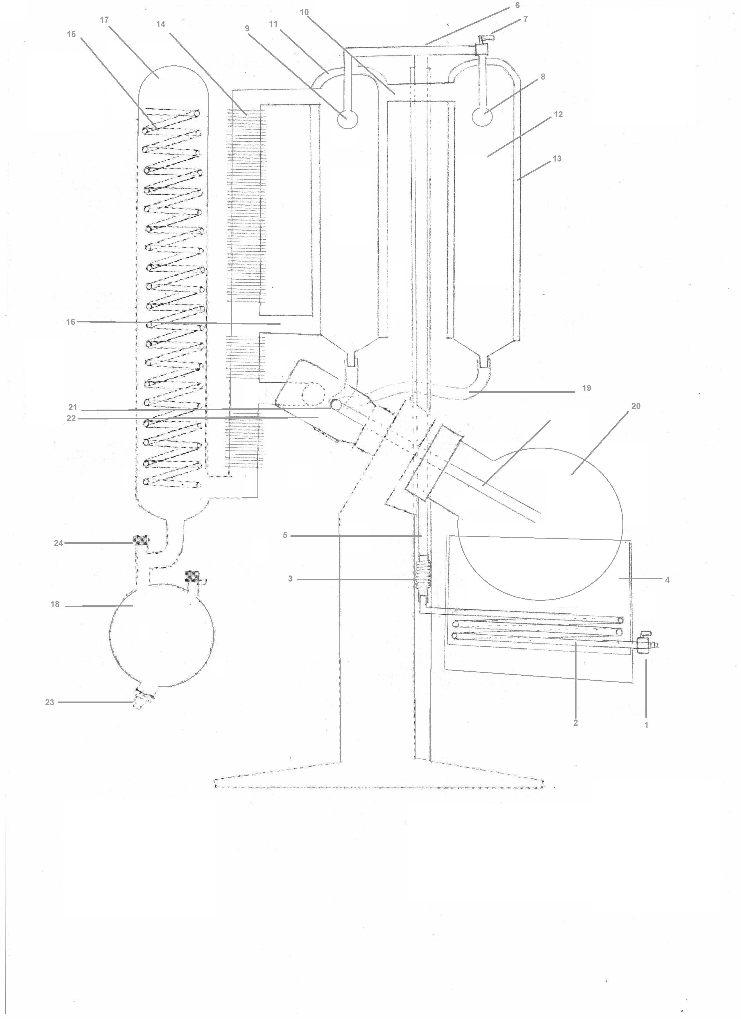
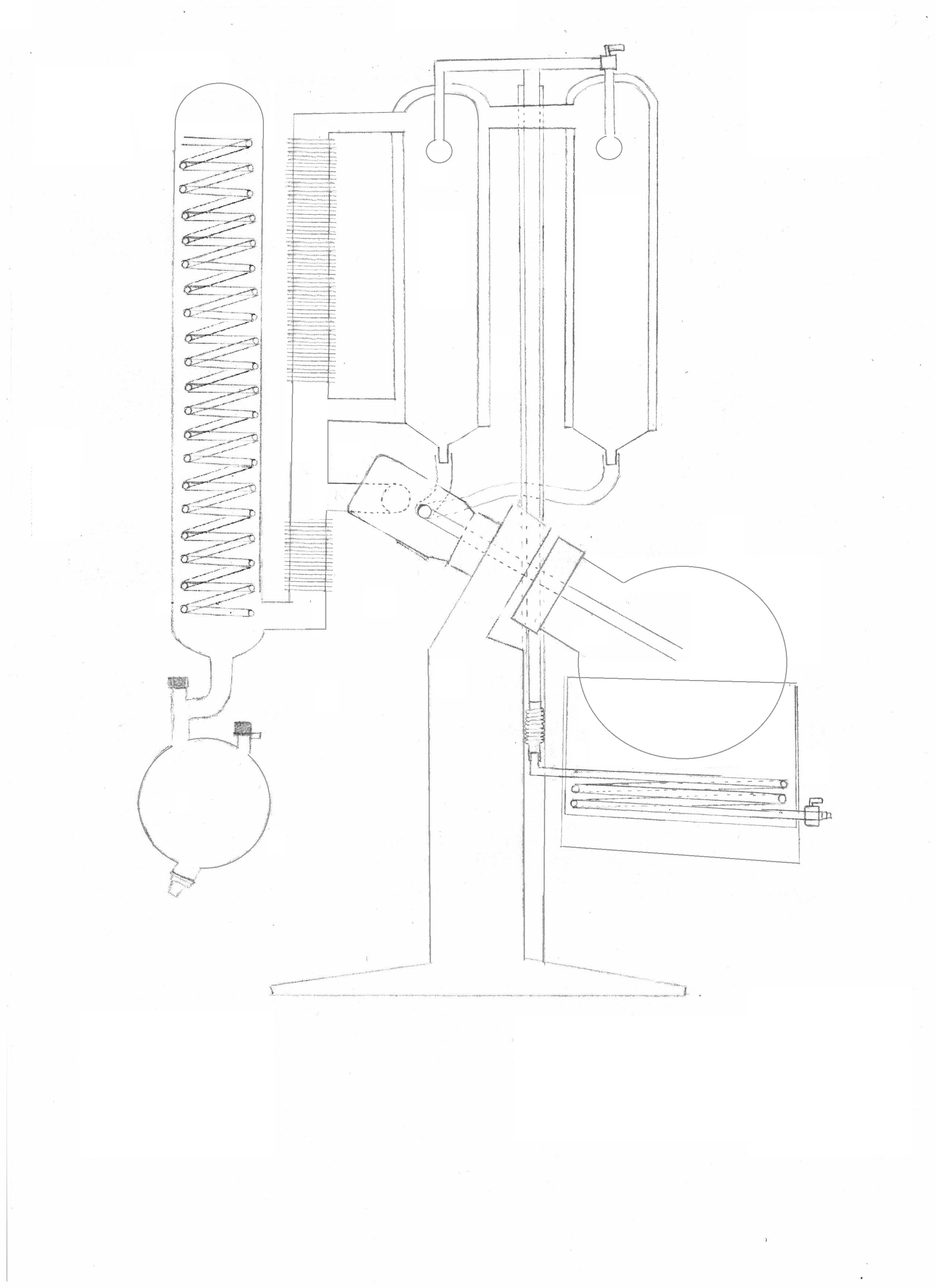
Internal pressure in the machine is reduced by a vacuum pump which allows the sample to be sucked through flow metering valve (1) and into coils or pipes (2) placed in the heated bath (4) of the rotary evaporator. This causes the sample to be heated and the pressure inside the coils to increase. The sample is then routed out of the heated bath section and through expandable tubing (3), or flexible tubing with excess slack to allow the bath height to be raised or lowered while remaining fixed in an insulated pipe/tube (5). This pipe or tubing is wrapped with a tape type of heating element which acts as an additional heating zone for the material inside the pipe as it travels to the liquid manifold. This heated pipe is also insulated and can be routed inside of a long metal cylinder which may also serve as support for other parts. The pipe is connected to the liquid manifold (6) on top of the machine. The increased pressure inside the pipe along with the reduction in pressure inside the machine causes the sample to become almost instantly vaporized as it enters the lower pressure zone and this process is referred herein as “flash vaporization”. The remining liquid not vaporized is then sprayed into fine droplets through the spray nozzle (8,9) onto the wall of the flash vaporization chamber (12). The flash vaporization chamber includes an outer jacketed section (13) which can optionally also be wrapped with resistive heat tape that heats the walls of the chamber. Vapor created in the flash vaporization chambers is then routed to through a pipe (10) which connects to the outer jacketing of an additional flash vaporization chamber (11). The hot vapor transfers heat from any previous columns by flowing through the jacketing of any subsequent flash vaporization chambers and thus heating the walls of the chamber. The heated walls increase the vaporization of liquid sprayed on the inside of the column walls and also helps to partially condense the hot vapor flowing through the walls which increases efficiency and distillation speed. This can be repeated with up to four different columns increasing efficiency each time. The vapor and condensed liquid from the outer jacketing (11) is routed through a pipe (16) and to the cooling tube (14). The cooling tube is a metal cylinder approximately 3-5” in diameter with cooling fins. Vapor created from any other section is routed to the cooling tube which ultimately connects to the condenser section (17). An external cooling device is used to cool the condenser section. A common method of cooling is to use an external device to circulate cooling fluid through internal coils (15). Vapor routed to this section is condensed and is routed to the receiver flask (18) where it is collected. Any materials not vaporized in the flash vaporization chambers is routed through tube (19) into the evaporating flask (20). The flow into the evaporating flask can be controlled with a valve (21). The evaporating flask is partially submerged in the heating bath fluid and is heated and rotated. As the flask is rotated a thin film is deposited on the walls of the flask and as it spins gravity forces the sample down back into the lower portion of the flask. The moving of the sample reduces surface tension and increases the distillation rate for the last bit of solvent in the sample which can be hard to remove to desired levels. The vapor created in the evaporating flask is routed through the vapor manifold (22) and to the condenser section where it condenses and falls into the receiver flask and is collected. The collected material can be drained through drain port (23), by closing the receiver flask material valve (24) and opening the drain port.
see above
What a great idea I love it!
Extremely interested, DM me please. We’re currently shopping for a solvent recovery system for a new facility.
Please DM me with more info once pricing is available!