Okay, because I don’t have enough projects already:
Bossman finally approved building a central cryo chiller. Siccckkk. Been on my list way too long.
Now, we currently don’t do much heavy lifting at sub -40C because, well, it’s expensive. But as I keep adding more equipment and more demands, it’s getting annoying to have all these extra small systems that are non standardized. We don’t need anything like a $100k Huber 930W like all y’all running cryo ethanol or massive passive hydrocarbon systems BUT since we’re building a thing…
I’m not going to go -80C because I think I’m going to do better with a clever two stage single refrigerant design than cascade but it’s going to lose capacity quick past about -60C. That being said, 20kW at -60C is the spec for a 930W and I think I can beat that for less than $15k.
The system will be water cooled because fuck having that much radiator lol. I’m considering using some semi hermetic compressors that we pulled from some CRAC units that came in (we don’t need the refrigeration system, just want the coils and fans), but they’re a little weird for the task. Regardless, some serious active pressure control will be necessary. My contribution here in addition to the BOM and P&ID is going to be the control system to allow using a high vapor pressure refrigerant with standard compressors and not blow anything up.
Anyways, been talking about doing this for a while so y’all stay tuned. If anyone has a suggestion for a more ubiquitous big compressor that can be found used cheap than these copeland discus style semi hermetics, please chime in.
So somewhat simply, the plan is to use a bank of compressors to move the low temp, less dense vapor off the primary evaporator, cool the discharge gas, and then compress it further. This allows a compression ratio of ~ 100:1 which is great. The trick is how to get away with using a refrigerant that is sufficiently dense at -60C without exceeding the pressure rating at standstill.
Yes there will be a high pressure compressor and a low pressure compressor (a bank of these in parallel actually). I’m leaning towards r744 (CO2) for a couple reasons, cost being a major one. The intermediate temperature is one of the things I have to calculate, the goal is to match the mass flow of the low pressure and high pressure “stages”.
Basically, what we care about is the latent heat at our evaporator temperature (-60C) and the density at that temperature. The less dense the refrigerant, the more displacement our compressor(s) will need to have.
Here’s a chart of some options. I use a factor that is the density x latent heat which basically indicates the cooling per displacement. You’ll see that CO2 is actually a slightly better refrigerant than the super expensive and specialty r508b. The funny thing though is that it will turn into dry ice if it gets down to -78C, which is why you don’t see it in many cascade systems. Lastly, r404a which is the most common single stage low temp refrigerant is like 1/10th as effective as the CO2.
Unfortunately, the low side pressure is not the only question. We’ll be exchanging against our facility chilled water which is about 5C so I’m looking at the pressure at 10C. Unfortunately, CO2 may be a challenge here because I’ll need specialty compressors which can handle condenser pressures that high. Ruh roh.
Now filling a large system with r23 or r508b would probably blow half my $15k budget, so some trickery will be necessary here
Really Looking forward to this been wanting to do something like this for quite a while. Although my learning only got as far as trying to work out the sizing of capillary tubes. And I was lost from there… You using a coaxial heat exchanger?
I’ll probably be using plate heat exchangers depending on what I work out for the pressures (750psig is about the top end of what is inexpensively available for them). I’ll be using TXVs which are much more forgiving than cap tubes and also more effective. I may have to use an EEV or other stepper control valve for the interstage heat exchanger but I’m trying to keep this system as mechanically controlled as possible (mostly for my own time, but also to make the design more accessible for people here).
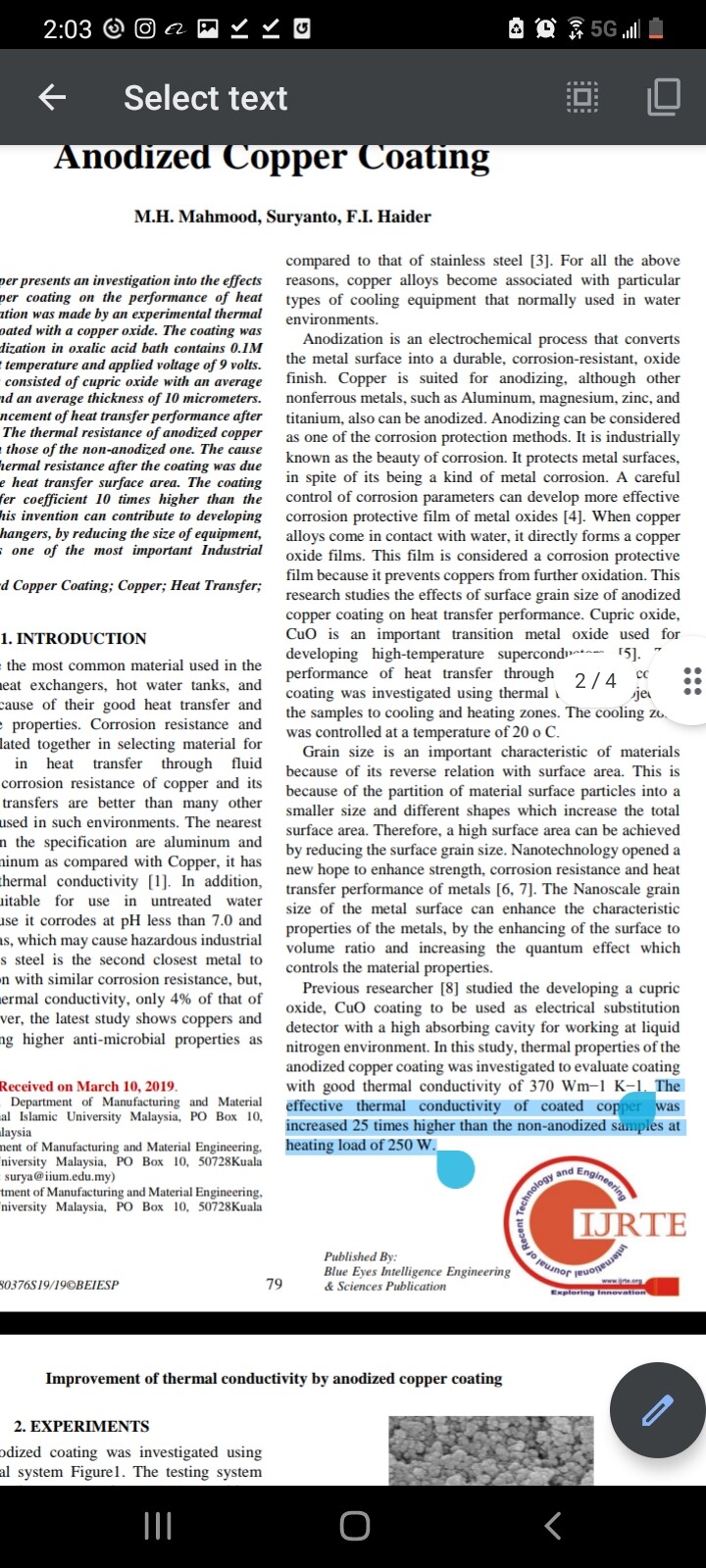
Unlikely. Anodization is line-of-sight which is obviously challenging in multipass heat exchangers. To my knowledge, brazing anodized copper would make for a poor mechanical joint. I also tend to doubt that anodized copper with the same film thickness as you’d commonly get on a heat exchanger is really 25x more conductive. Maybe 2x.
Ultimately, manufacturing cost makes it more feasible to upsize probably. Which is why you see most condensers/evaporators these days done in aluminum.
Edit: and yes, I will continue working on this thing so keep watching for updates. Sometimes shit just comes up lol
I don’t think process scale or manufacturing are the reason why this wouldn’t work, i also imagine that nobody would try to solder a pipe without removing the oxide coating. I certainly doubt the heat transfer improvement they claim but the idea sounds pretty solid to me. Increase in surface area should translate to at least some increase in heat transfer.
I don’t want to clutter your thread can I dm you about this?
Nah keep it here. These are the little burrows treasures for people who like to read on this forum.
The big issue I still see if the line of site aspect. I suppose if you were doing a refrigerant to air HX it would be a lot easier to anodize just the OD of the tubing before removing it from the ends curing the cutting process and then brazing. This kind of seems like it would mostly be applicable to applications where getting the HX as small as possible (e.g. aerospace) would make it worthwhile but not worth the effort for most normal applications.
I’ll also note that I don’t have a ton of experience with copper HXs (or at least, not any heavy design) because most of what I deal with is stainless. Which is a terrible heat transfer material lol
I also want to point out, this has a lot to do with the wall thickness of the tubing. If the tube is mostly coating, increasing the surface area of the copper may be meaningful but if (as is usually the case with refrigeration or process fluids) the copper is particularly thick, the limitation is the transfer across the bulk. That is, the surface of the copper may be heated very rapidly because of increased fluid interface, but that heat has to be transferred through a bulk of copper and that can’t be sped up at all.
I would think that something like this in an air cooled application would suffer from contamination. Lots of small shit like dust sticking to the coating and ruining the effectiveness.
Mmm I think one of the major benefits of anodization is intentionally reducing the oxide layer thickness. Also, generally copper is a weird material to use for liquid:liquid heat exchangers. On the refrigerant side, there should never be oxidation because there’s no air or water, and it’s all oiled.