That’s my first guess without looking at the manual as well. Depending on the level of PLCness that inhabits the VFD, the analog input is likely only really usable as a frequency reference or modifier.
Some of my VFDs could probably be taught to do that trick, but it would be much simpler to do it with external controls.
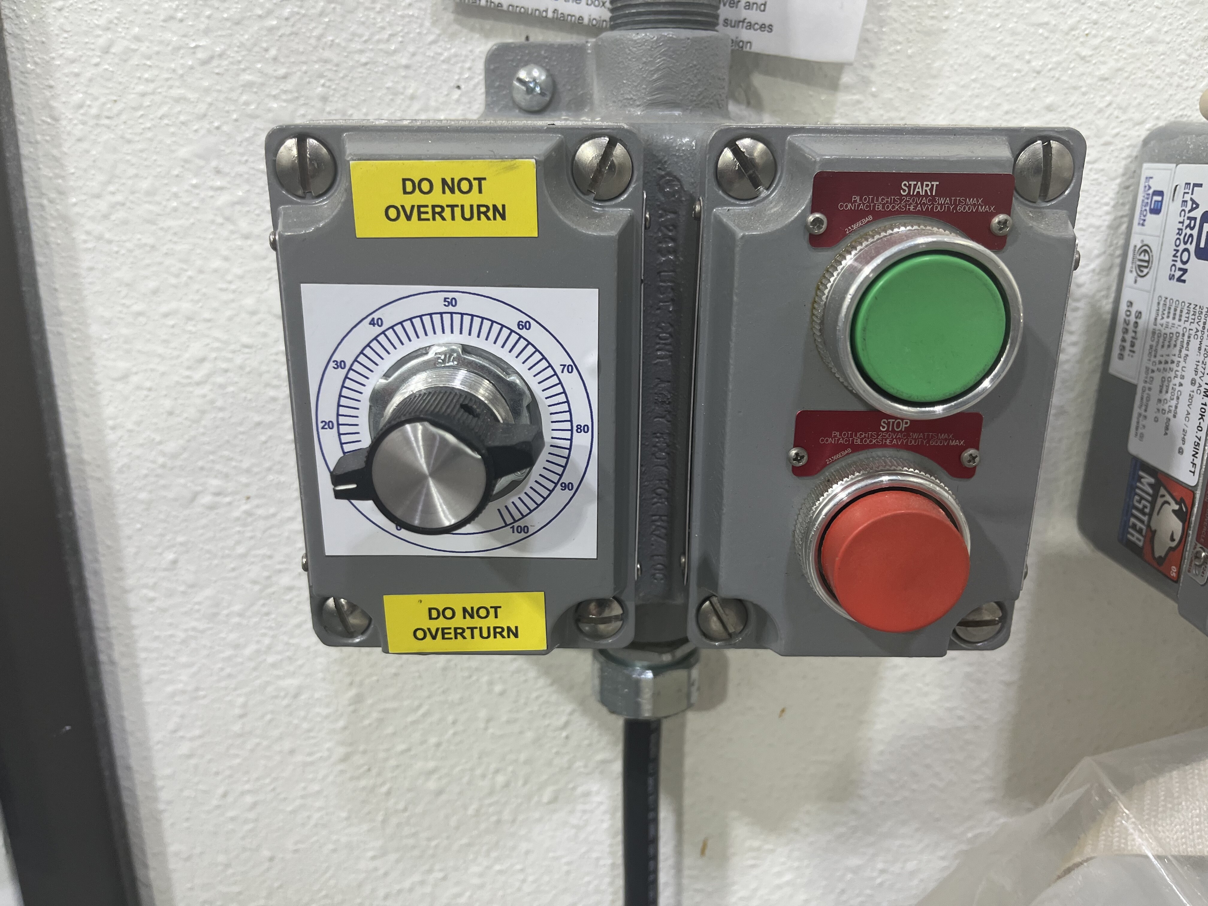
@ExtractionBoothLady; yes, It does currently control speed. We had the guy that installed it program it to do that.
@Lincoln20XX yeah, so the backup plan it to ask it to do what the green button says, but only for so long. Which might be possible without the timer relay based on a superficial glance at said fine manual.
…asking where my timer relays are is probably another approach
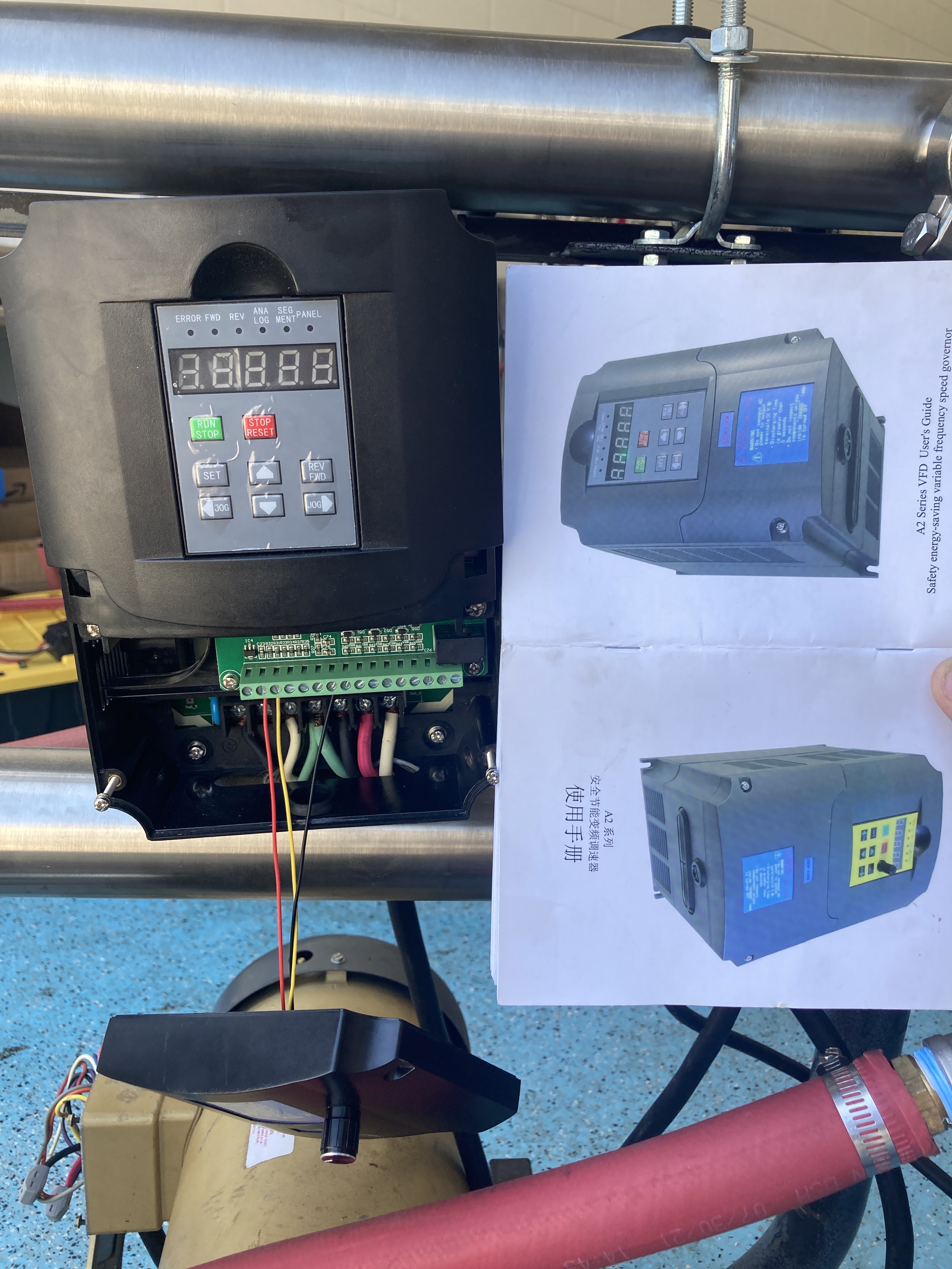
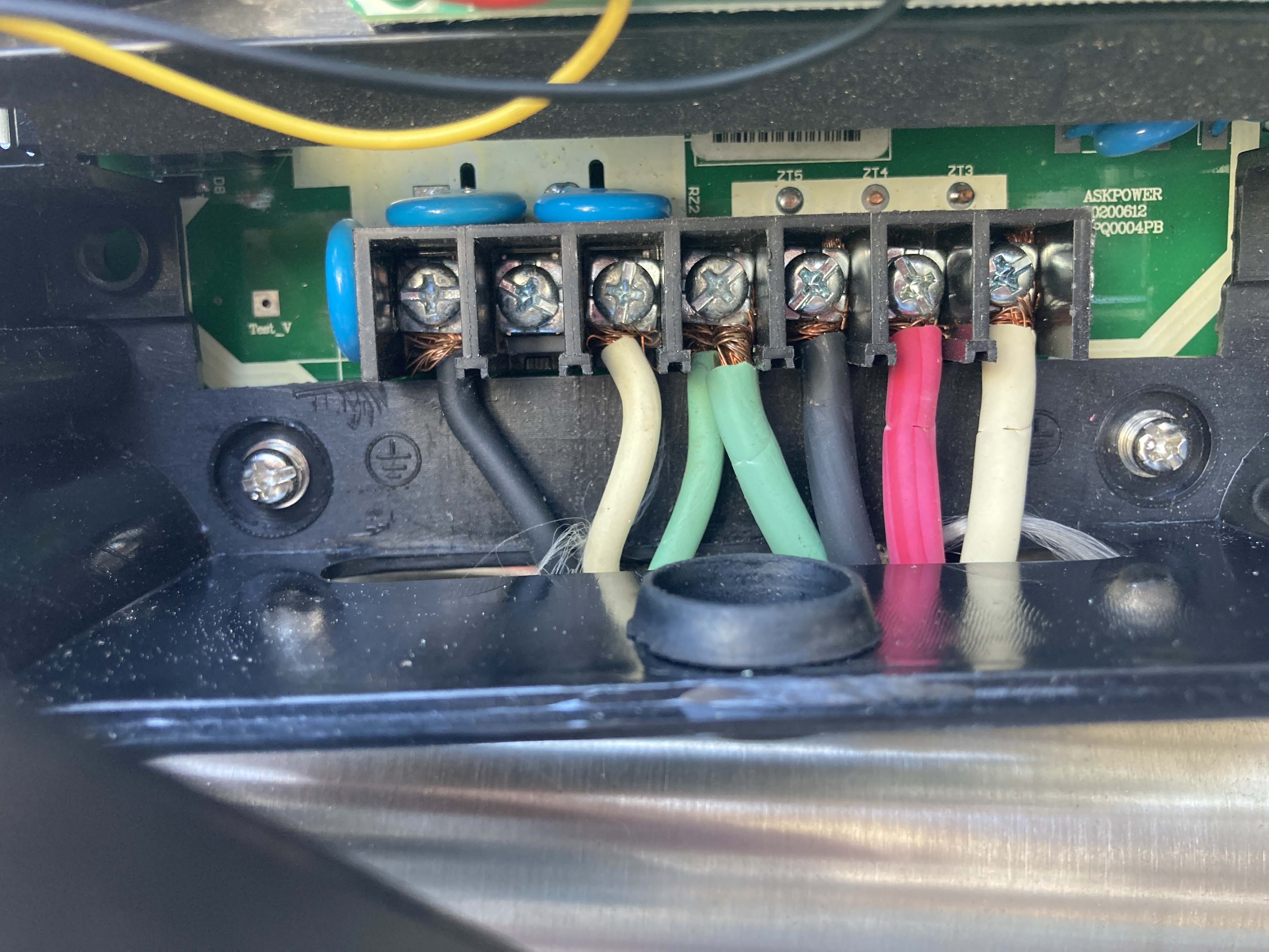
Wasn’t sure where to post, but I am troubleshooting a chinese VFD with a 5hp baldor motor for my high pressure pump. I believe I have all of the motor wires connected correctly, and I am running out of settings to change on the VFD.
I have tested voltage on each phase going into the motor and am getting ~112v to ground, but only around <30v phase to phase. The VFD makes the high pitch whirr like it is spooling up the motor, but the motor doesn’t spin. I have swapped legs to see if that played any effect. I have removed the fan shroud and confirmed that the stator is not siezed and will spin freely. I will be trying my 1hp vfd and see if that can manage to spin up the motor, but I was curious if any elechickens around here might have some ideas on what to try next.
Edit: I was able to get the motor spun up with the 1hp VFD but eventually ran into the current limiter. Anyone have any experience with these VFD’s?
Okay, so I figured it out. I ran the “Max Motor Frequency” parameter down to 60hz from 400hz, and changed another setting that I can’t remember, and it started chooching! Not really sure that would have held it up, but it’s working now!
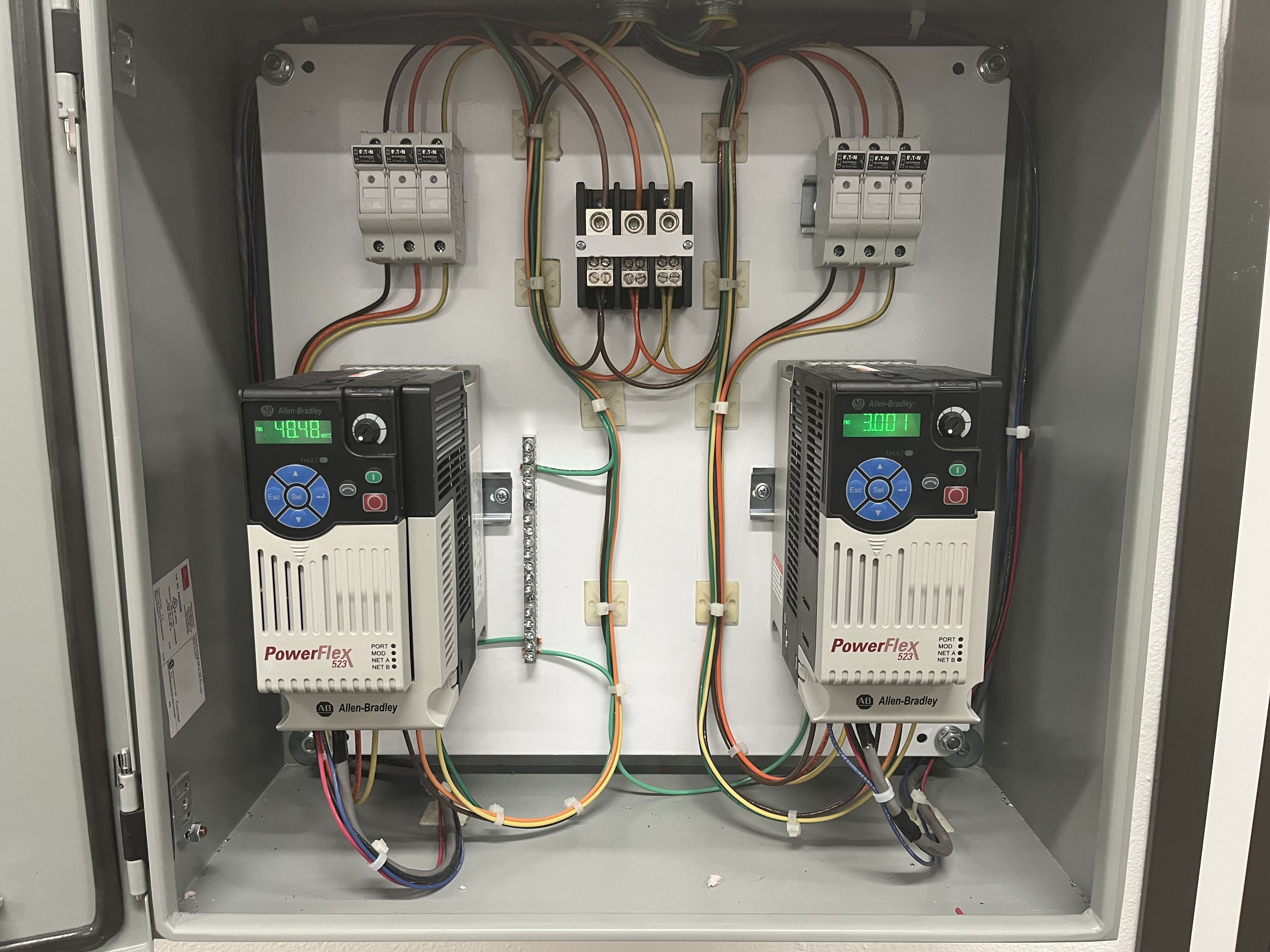
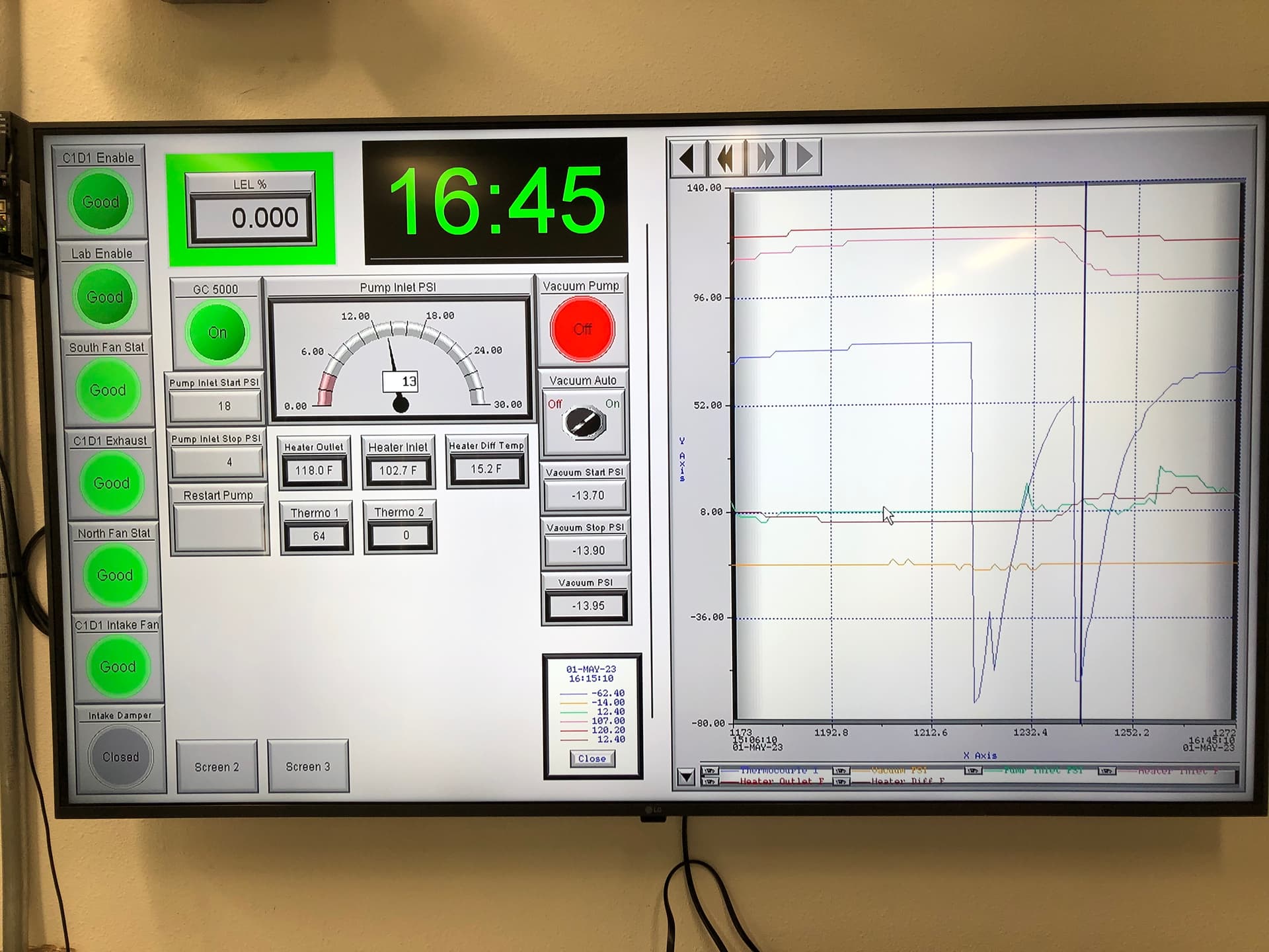
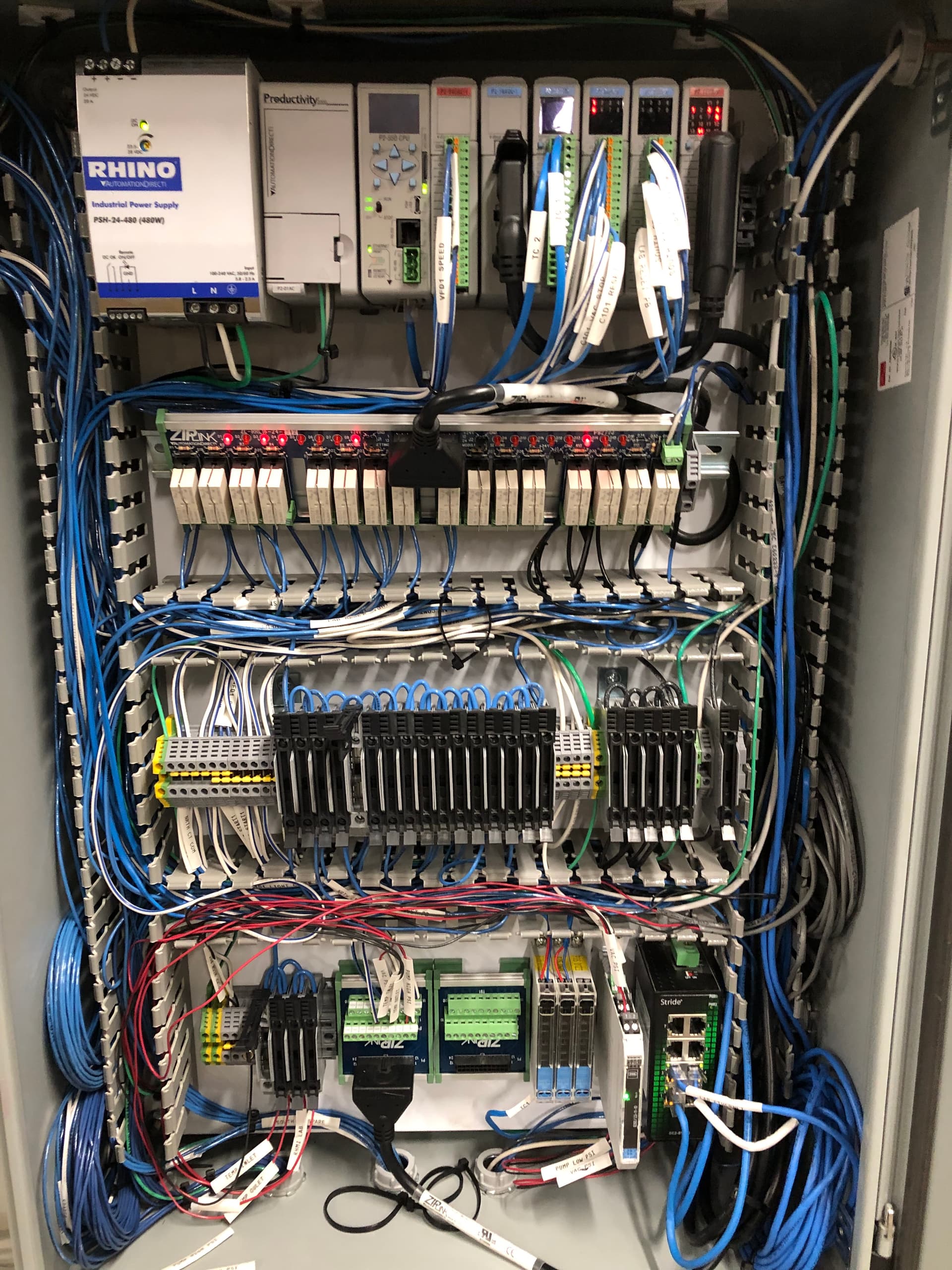
Automation Direct HMI for the win, I use their headless HMI hooked up to a monitor and their productivity 2000 plc hardware for control.
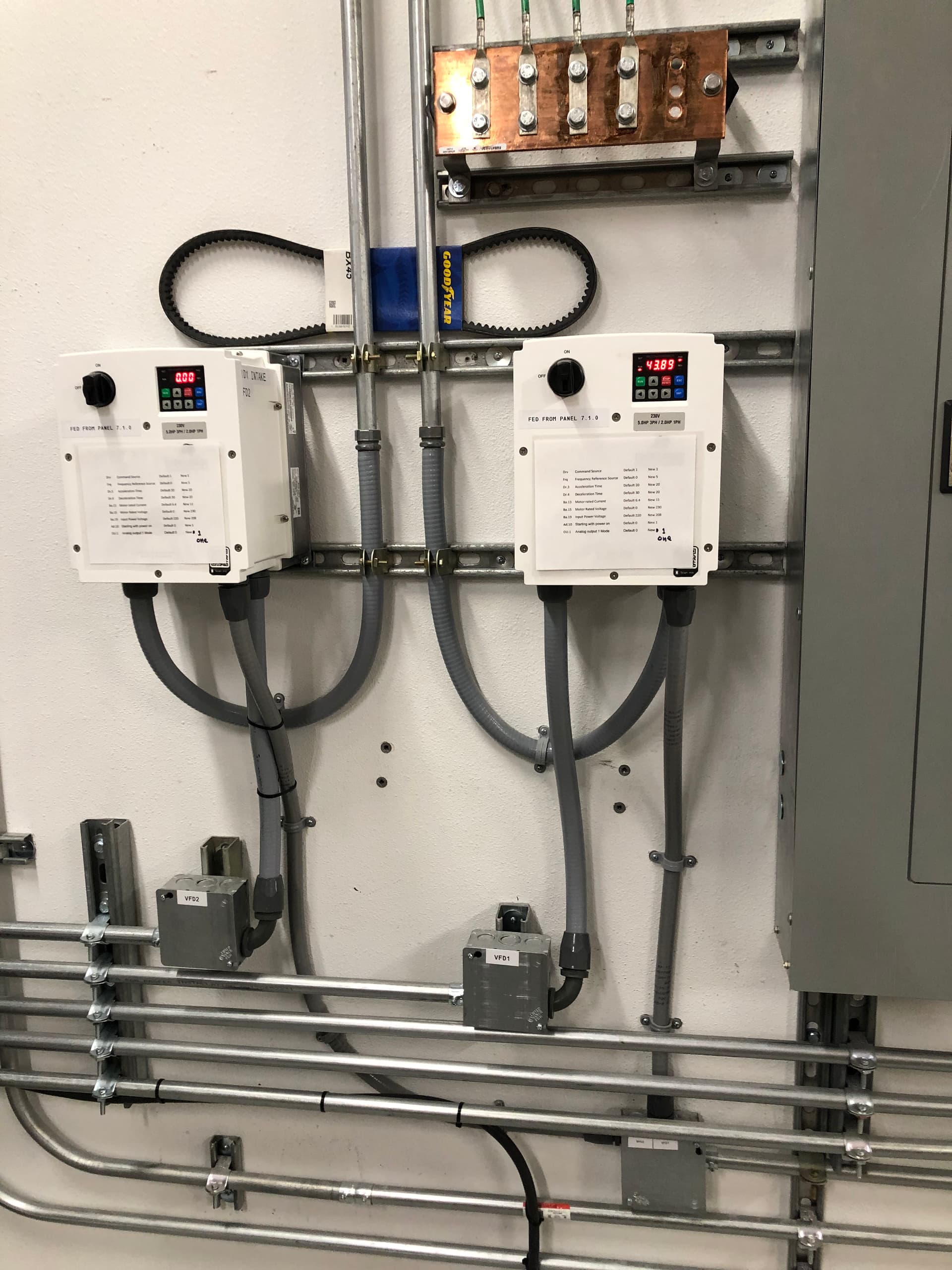
If you guys and gals get into customizing VFD parameters (2 wire, 3 wire, start/stop, speed ref, dig inputs outputs, npn/pnp, sinking/sourcing, DC boost, volts per Hz, vector control, etc…) give me a shout. I have 20+ years experience designing, building, and maintaining systems that used VFDs.
Note the parameter changes from default, printed laminated and taped to the VFDs. Do the next person a favor and document parameter changes from default.
From memory the 525 is a very basic allen bradley VFD. It does not have advanced control capability to take one of the analog inputs and scale it and then use it for logic functions like a timer. That is exactly what a PLC or PAC or computer comes in, you tie in a device that can execute logic (a program) and update outputs. You probably have ethernet IP on the 525 and for sure digital/analog inputs. Ethernet IP can control everything from a PC or PLC/PAC but is more complex. Digital/analog inputs are typically thought of as simpler. for example your potentiometer is wired to provide a voltage speed reference to an analog input, then start stop push buttons to digital inputs. The timer relays on the start/stop circuit will work and probably be the simplest solution bur I always recommend PLC PAC as they are more versatile but more complex.
Thays awesome!!! Be sure to document the parameters he changed, aka programming. I quickly searched the parameters on that drive and suspect he utilized the timer function parameters similar to below.
Timer Function
Digital inputs and outputs control the timer function and are configured with
parameters t062…t063, t065…t068 [DigIn TermBlk xx] set to 19 “Timer Start”
and 21 “Reset Timer”.
Digital outputs (relay and opto type) define a preset level and indicate when the
level is reached. Level parameters t077 [Relay Out1 Level], t082[Relay Out2
Level], t070 [Opto Out1 Level] and t073 [Opto Out2 Level] are used to set the
desired time in seconds.
Parameters t076 [Relay Out1 Sel], t081 [Relay Out2 Sel], t069 [Opto Out1 Sel]
and t072 [Opto Out2 Sel] are set to 25 “Timer Out” and causes the output to
change state when the preset level is reached.
Example
• Drive starts up and accelerates to 30 Hz.
• After 30 Hz has been maintained for 20 seconds, a 4-20 mA analog input
becomes the reference signal for speed control.
• The timer function is used to select a preset speed with a 20 second run
time that overrides the speed reference while the digital input is active.
• Parameters are set to the following options:
– P047 [Speed Reference1] = 6 “4-20mA Input”
Time
Logic In 1
Logic In 2
Frequency
Start Step 0 Step 1 Step 2 Step 3
Time
Logic In 1
Logic In 2
Frequency
Start Step 0 Step 1
Velocity StepLogic, Basic Logic and Timer/Counter Functions
– P049 [Speed Reference2] = 7 “Preset Freq”
– t062 [DigIn TermBlk 02] = 1 “Speed Ref 2”
– t063 [DigIn TermBlk 03] = 19 “Timer Start”
– t076 [Relay Out1 Sel] = 25 “Timer Out”
– t077 [Relay Out1 Level] = 20.0 Secs
– A411 [Preset Freq 1] = 30.0 Hz
• The control terminal block is wired such that a start command will also
trigger the timer start.
• The relay output is wired to I/O Terminal 02 (DigIn TermBlk 02) so that
it forces the input on when the timer starts.
• After the timer is complete, the output is turned off releasing the preset
speed command. The drive defaults to following the analog input
reference as programmed.
Note that a “Reset Timer” input is not required for this example since the “Timer
Start” input both clears and starts the timer.
184 Rockwell Automation Publication 520-UM001B-EN-E - February 2013
Appendix D
Depending on how fast it was set to accelerate from zero to the speed you had it set at, its possible that it went from a hz speed where it could have made enough torque to spin, to well past that in a very short amount of time, to where torque was dropping off very quickly because it was so far above motor designed peak torque, which is most likely at or near 50-60 Hz
Programming is documented. Perhaps not well enough that I could duplicate it without referencing the fine manual, but I believe the details are all there.