The resistor is doing its job, and dynamic braking pulls the speed down quickly, the problem is that once it kicks off, the 150+ lb rotor then freewheels for several min.
Enabling DC hold on an ABB ACS355 VFD likely involves configuring a specific parameter. Here’s how you might achieve this based on the ABB ACS355 user manual:
1. Ensure Local Control:
The manual mentions switching the panel to local control mode before modifying parameters [ABB ACS355 user manual, pg 72]. Look for a key or button that switches between local (LOC) and remote (REM) control on the control panel.
2. Locate the DC Hold Parameter:
The user manual doesn’t explicitly mention “DC hold” as a parameter. However, it discusses settings related to DC control. Look for parameters related to DC braking or injection in the manual’s settings section [ABB ACS355 user manual, pg 138-139].
3. Enable the DC Hold Function:
Once you locate the relevant parameter (e.g., enable DC braking), consult the parameter description in the manual to understand how to set its value to enable the DC hold function. It might involve changing the value to “1” (ON) or another specific setting.
It has the specific setpoints for the drive configurations.
And includes the calculations and such - there appears to be some mention of settings for connected braking resistors.
And there is another supplement on their website… it has so much more in it. Which includes the acceleration and deceleration ramp specifications.
If I remember correctly - you can define what the ramp looks like with stepped slowing which might actually be faster than just “Off and Wait”.
You probably already have all this stuff. Are you already bringing it down to 1? From your image I cannot tell how you are stepping.
Perhaps, maybe using the e-stop ramp? Might stop faster, but could cause more wear and tear?
The second link talks about the spindle turning for a long ass time…they said an hour.
The first link mentions DC Hold Parameters - for synchronized stopping. And it also has the steps and points to the equations for looking at the ramp (with some terrible examples).
We had the same issue, but it was with an automation direct drive.
I seem to remember that solving it involved changing some combination of the stop, DC braking, and DC hold functions.
This page looks like the right place to start. Perhaps set your stop mode to coast, enable DC braking, set your current, and increase the time until you get to stopped.
I suggest tossing some math at it to be sure but if it’s an oversized resistor (which it appears to be) and if it’s a low duty cycle (not stopping all that often) you might be able to get away with 100-150% braking current.
I’ve always used 150% but I also massively oversize my braking resistors.
I had skimmed through it…appeared to be for multi-drive configurations with a common DC bus, with nothing to offer on braking except feeding (the) other drives on the same DC bus.
second and third read through didn’t get me any further.
neither did the other supplement.
the image is a trace of the “speed” the drive is reporting (no encoder, so not actual speed)…it shows the drive slowing from 60hz to 15hz over about 30 seconds. (I believe) I’m running with the defaults of 5sec acceleration/decceleration, and that the current limit is the control point here. once the drive thinks we’re at zero, it shuts off and we coast.
I’ve got the guy who put the panel together coming by tomorrow to look at the problem, but he’s a youngster and not very familiar with ABB drives.
having played with most of the other relevant settings I’m now of the opinion that
once the drive thinks we’re at zero, it shuts off and we coast.
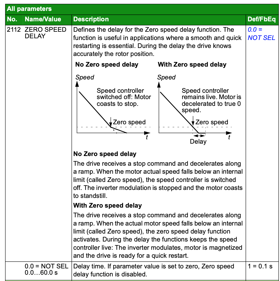
is actually the key, and I need to set the “zero speed delay” to something other than zero.
If you post a full parameter list (easier to do if you’ve got it connected to a PC with commissioning software than if you’re manually setting the parameters from the panel) I can make a few suggestions.
The big issue is that while you’re doing a “ramp to stop” deceleration and burning some of that energy off on the brake resistor, once you’re below ~2-5 Hz depending on setting the drive basically believes that you’re at the zero speed and isn’t going to do any more work. In either V/F or open loop vector control modes the drive doesn’t really know how fast motor is spinning once its under a certain threshold and the drive isn’t actively putting power into it. For most applications that don’t have a lot of inertia this works fine, but obviously this application has a whole lot of spinning inertia
If your decel ramp is acceptable other than the last little bit where it keeps spinning that says your brake resistor is working (you can tell because its prob getting good and warm while decelerating)
What is your parameter 2602 is set at, you likely want it to be at “full” for flux braking.
Also want to know what parameter 2104 for “DC Hold control”, 2105 for “DC hold speed”, 2106 for “DC Current reference” and 2107 for “DC brake time” are set at, from what I read it looks like DC hold control won’t actually do anything until the drive output is below parameter 2105 which is exactly where you seem to be having an issue
pretty sure I touched ALL of those today. changed the behavior, but never achieved my goal of an actual stationary rotor.
exactly!
…and I suspect 2112 (zero speed delay) is where I can combat that issue (see above). LOTS of inertia in this application.
so you think you’re done huh? How about you sit there for a couple or 10 seconds before cutting the power…you know, just to be sure you’re actually done…
no, I don’t have a PC hooked up to it, might look into that as an option, but I’ll get back to you tomorrow with all of those parameters either way.
@Lincoln20XX showed the relevant (2104-2107) parameters upthread.
Of note is that drive is (currently) in “Scalar:freq” mode (9904 = 3).
So DC HOLD (2104 = 1) doesn’t work…I’m not certain what this means for 2104 = 2 (DC Braking), but I’m working under the assumption that DC Braking should work in Scalar: Freq mode. If not, I’ll figure out how to get it into Vector:speed mode.
I’m doubtful that changing your zero speed delay is going to fix this, as from what I’m reading it does more for a fast restart versus actually slowing the physical speed of the motor to zero. Keep in mind “zero speed” is just a parameter defined threshold in either Hz, RPM or current along the deceleration ramp.
Idk what is wrong with ABB that they can’t call their modes the same things most other manufacturers do, but I think scalar frequency is what everyone else calls V/F mode. It basically means the accel and decel ramps move along a straight line where one axis is voltage and the other axis is frequency
Either mode should not have problem with DC resistance braking but an IR thermometer or a close hand to your braking resistor during a deceleration cycle would tell you the answer for sure.
I’m guessing the scalar freq mode doesn’t like DC hold after frequency reaches zero because of some bad referencing/programming, who am I to judge, someone who works on stupid shit literally all the goddamn time.
To change to vector speed mode change 9904 to 1
Make sure your motor dataplate parameters are entered correctly in the following: 9905, 9906, 9907, 9908, 9909. 2002 if you’re not exceeding (what I’m guessing to be) 60 Hz at full speed
For the rest of them I’d suggest trying the following:
2602: 2 (full)
2104: 1 (dc hold)
2105: 50 (this is an estimate of when you want it to start injecting DC braking current, assuming your motor is an ~1800 RPM rated motor)
2106: 50 (percent, may have to be bumped up if you need faster stops than what you’re getting)
2107: 10.0 (seconds, may have to be bumped up if it takes longer than that to completely stop turning, or dropped down if it stops right away)
I haven’t dealt with ABB directly for a while but in the past idk, decade or so they’ve been so ridiculously fragmented that you have to talk to one department/vendor for a motor, a different department/vendor for a PLC, and a different department/vendor for a VFD, even if you’re working on a project that uses all 3 (as some centrifuges do). It’s ridiculously frustrating and mind bogglingly fuckin stupid
I’ve only tried them once upon a time…my recollection is it wasn’t worth the effort.
It’s possible they do and would be happy to help, certainly worth throwing 30 min at the problem.
Absolutely!
I had thought the kid who programmed the PLC and HMI had done that. He got close. Most importantly he did have max current correct. Name plate was visible when he had access to machine, but is covered in a rather inconvenient manner now that we’re (almost) ready to rumble. I dug out the pictures I took when it came in the door when I got home last night, and will make some minor adjustments first thing.
Yeah, actually I was concerned with how that might interact with the PLC & HMI.
Know how, not certain I understand the implications…would have been a better characterization
As far as zero speed wait, I’ll let you know. Then proceed as suggested. Thank you AGAIN for all your assistance (over the years).
Worst case I have a local who likely knows these drives well showing up on an unrelated matter tomorrow, so if I can’t solve it, I’ve got a fall back plan.
Now achieving full stop in about 65 seconds. Which won’t stop someone determined to injure themselves, but is fast enough that my operators won’t be overly tempted to open the thing while it’s still spinning.
Most of the speed comes off via the braking resistor, in the first 35-40 seconds …thermal camera says it’s getting to about 100C.
Then at 50rpm the DC injection is enabled at 75% for 30seconds.
I can’t get a good view of the motor, or get my hand on it (which is how I would usually measure temp), but sneaking the thermal camera in as best I can, it doest’ show any significant heating of the motor… in production I’m only doing this once every few hrs, so I think we’re good.
Drive enclosure smells warm, and drive is at 45C when I’m done… doesn’t seem excessive, but I plan to keep an eye on this.
Thanks again to those that helped guide me (@greenbuggy, @Cassin, @Lincoln20XX)…not that calling the OEM (ABB) wasn’t a valid suggestion @MagisterChemist…just that I did not actually call them.
The local expert I asked actually used a “phone a friend” to confirm y’all had pointed me in the correct direction.