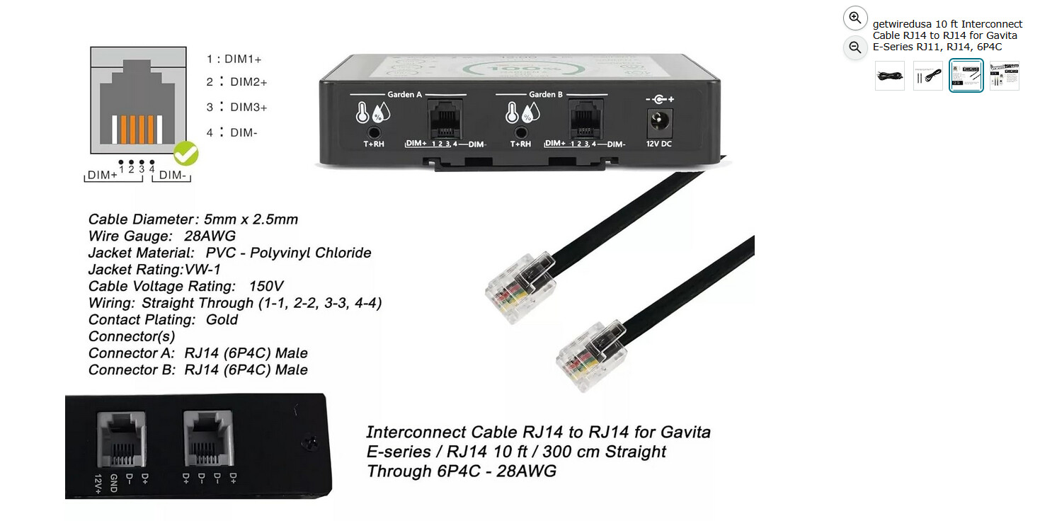
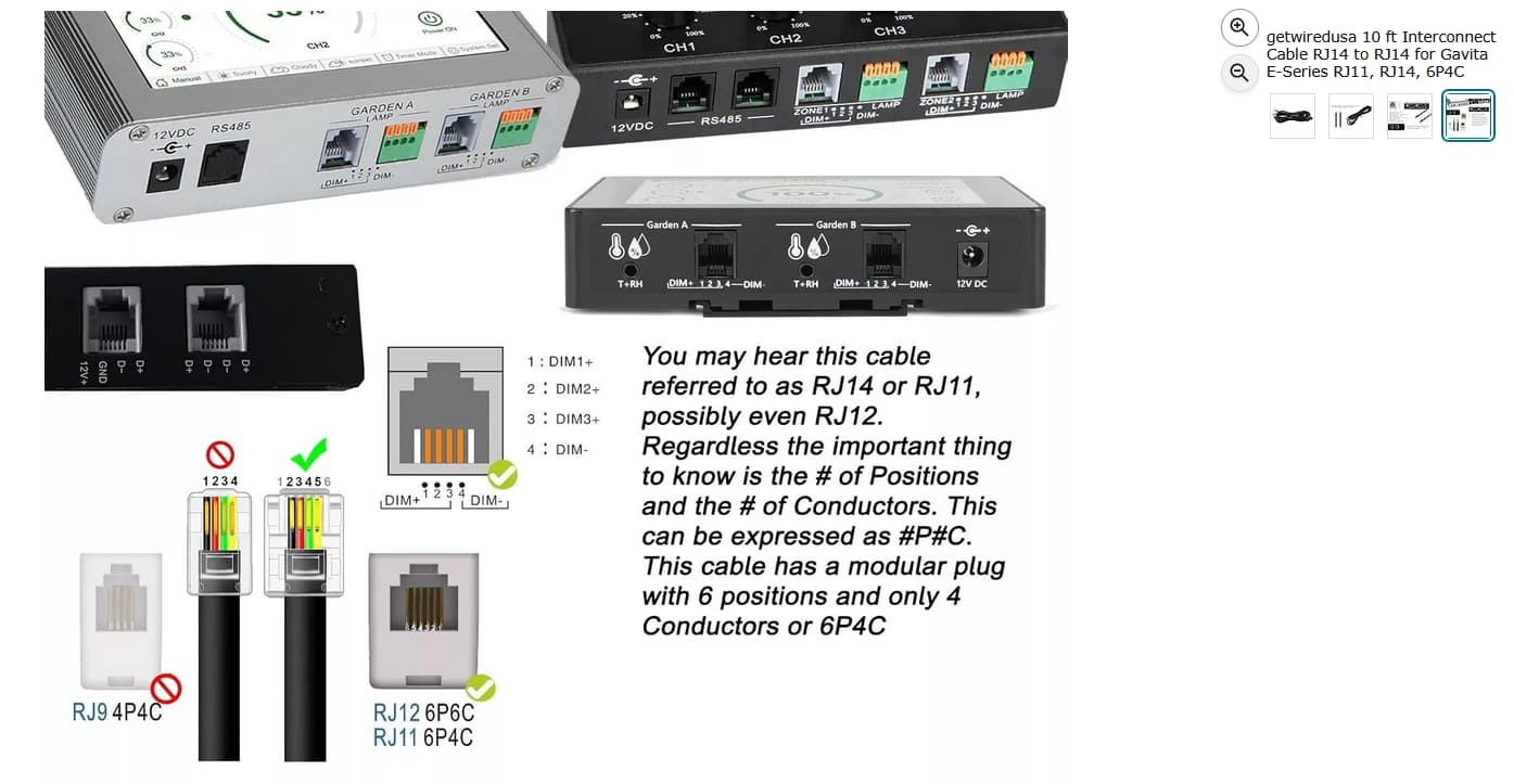
I just wired some gavitas to a plc. I couldn’t find a gavita low voltage diagram, so I had to reverse engineer an el1. Just wanted to post what I figured out hoping it will save someone some time. The center 2 pins (red and green wires) on the rj9/rj11 are dc-. The outer pins (yellow and black wires) are dc+. Below 5vdc the lights are off, 5vdc=50%, 10vdc=100%, linear. Max voltage is 11.5v.
13 Likes
What’s your controller end look like & the wiring on the unit itself?
If it’s the unit i have on my mind it should just be a simple wire twist for dimming sadly… it’s hilarious but yeah…
1 Like
I think an Arduino or Raspberry Pi could easily clone one of these if the low voltage wiring was well documented.
China did a quick and affordable spin off of these units, although the interface was terrible.
5 Likes
My control end is an automation direct domore plc, the gavita phone cords are wired directly to onboard 0-10v analog outputs. I am waiting on some dc boost modules I ordered to boost my 10v to 11.5v. It’s setup in a greenhouse with par meters. The back end is a PID controller in the programming that is set to maintain 1,000 umol.
3 Likes
Arduino or pi could easily be set up with a 0-10v driver. I’m just comfortable with plc ladder logic and needed a lot more i/o than most pi boards have. I picked this plc up for $100 on ebay, and all automation direct plc’s have free software. The gavita low voltage is incredibly simple, if you have any questions ask away.
3 Likes
Hi @emdub27! I’m interested in control a Gavita pro e-series from an arduino and the only info about this was your post. I don’t know if you are currently active in this forum or if this message will arribe to you but if it does could you help me on some questions?
The dc- and dc+ pins on rj11 connector (red/green and yellow/black as you said) can be connected to the same dc source or there is one pair of pins for other purposes?
You said that from 5vdc to 10vdc there is a linear dimming from 50% to 100%, for example 7v dc is 70% of power? Then 11v is 110%?
Thank you!
The red and green pins are connected to each other inside the ballast. The yellow and black pins are also connected to each other inside the ballast. One DC voltage source is all that is needed.
Correct 11.0vdc is 110% and 7.0vdc is 70%. In my case I had to use a dc voltage boost module to get above 10vdc.
I have confirmed the same siring and voltages also work for nanolux as long as you buy the usb to rj11 adapter.
2 Likes
This info is gold!
Thank you so much for your investigation and share with others, very useful!
2 Likes
So I can make a dimmer for cheap?
Yes you can dimmer a Gavita light with cheap hardware. Also you can do the day/night cycle without any timer, just an arduino that turns on/off the gavita applying more than 5V to the rj11 port.
1 Like
Did you use a I2C DAC Module to output that voltage signal?
Also, i noticed the RJ9 from the Gavita EL1 outputs as follow:
Pin 1: -11.5V-0 | Pin 2: GND | Pin 3: GND | Pin 4: 0-11.5V
How did you manage to convert this with a DAC from an arduino or esp board?
Thanks
Im looking to do this as well and curious if you needed a signal isolator\amplifier\conditioner on the output for long strings of lights?
Thank you for doing the hard work, there is nothing out there that indicates the cable pinouts.
I am in the process of connecting a plc to two 1700e fixtures using the e series adapters. Is it still necessary to have the dummy (terminator?) plug in one of them? The adapters I got did not come with the dummy plugs. Would you know what the pinout is for them?
Thanks!
thank god I found this post. I have 15 old 1700e’s that I am in the process of daisy chaining together to a growlink setup with 30 other lights and I was using ChatGPT and it said typically red is dc+ and green is gnd. So now I know I can daisy chain them together using rj 11 splitters without buying that 100$ adapter for each light and I will take
Yellow & Black Tie both into the purple (DIM+) WAGO block
Green & Red Tie both into the grey (DIM-) WAGO block
@emdub27 so this def did not work I am currently trying to contact gavita to see how to get it to work correctly. Chatgpt says I can just take 18/2 wire and put positive to the purple and the white negative to the grey and it didn’t work when connecting to my growlink lightlink controller so any help would be much appreciated
For the love of god do not take ChatGPT’s advice for anything that can make an entire building go up in flames
4 Likes
well can you give me advice on how to wire this to my growlink links lightlink controller cause I cant get them to daisy chain to my other lights and then back to the controller
Those controllers suck. Just wire them to a gray box. Done. Make multiple banks.
I never would use those things in a million years when I could just power on the lights without extra bells and whistles. Just another point of failure.
1 Like
because my whole grow is setup on the growlink links system. Lights, Co2, environment, batch tank, ph, ppm, ec, humidity, temp, lux, feeding, water level, literally everything
Ugh dude i’m so sorry, that sounds like a nightmare to have to have it hooked up all like that
Let me take a look at this. I actually have a few.
Found those on amazon for a product which illuminates a bit of the wiring at least. Do you have to hard-wire them to the controller itself? Let me see if I can find some pics of the controller on google so I can see what you’re dealing with
Have you used a multimeter to ensure that proper voltage is coming out when it’s all said and done, also?
1 Like