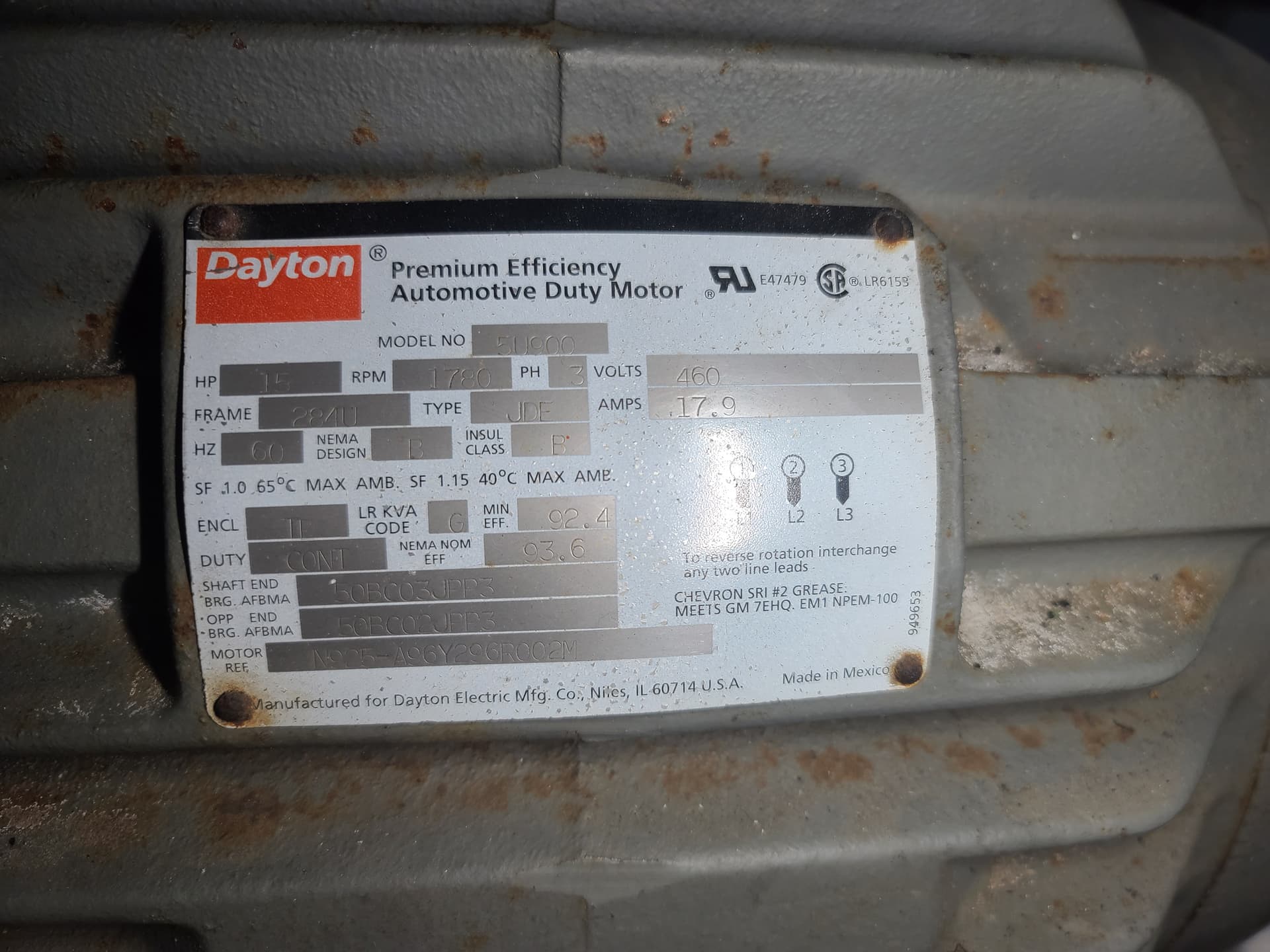
15hp 3 phase motor in good shape, free if you pick it up.
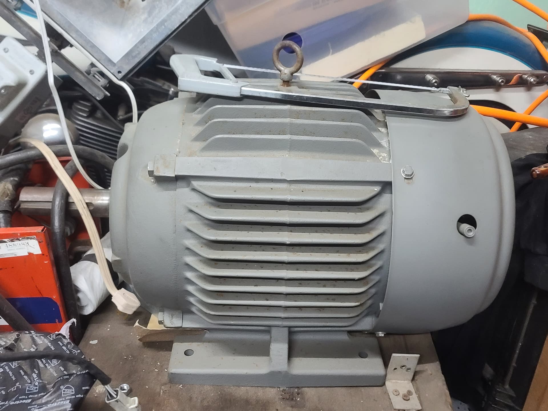
1⅝" Shaft diameter.
DM me if you want it.
Acquired for a client who wanted to setup a membrane system and then he cat on me.
Bump take this shit off my hands.
Bump. Not opposed to strapping this thing to a pallet and shipping it out if someone wants to pay for the freight.
It would be a shame to do to such a nice motor but you can always crack it open take out the copper and sell it.
Hard to believe no one’s taking you up on taking this for free.
While it is a continuous duty motor, it’s not rated to be operated with a VFD.
Which probably makes it much less useful to this crowd.
I’m not gonna take it apart for the copper, it’d just be a waste of my time
Put it up on eBay
I could. Just figured someone here might get a use out of it so I’m gonna hold off for a couple more months before I put it up for free on craigslist.
I’m not sure why that motor wouldn’t be suitable for a VFD, please explain?
Insulation class B aren’t suitable for use with VFD.
Guess you could run it on a vfd if you wanted but it wouldn’t last very long…
To expound, I read up a bit here on the different insulation classes:
Electric Motor Insulation Class - What is It? (hecoinc.com)
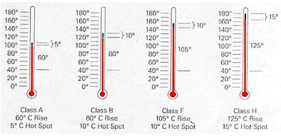
The purpose of NEMA motor insulation classes is to describe the ability of the motor winding insulation to handle heat. There are currently four electric motor insulation classes in use: A, B, F, and H (although there are also N, R, and S classes). Of these four, B, F, and H are the most commonly used. These classes specify the allowable temperature rise from an ambient temperature of 40°C.
- Class A Insulation:
- Maximum Temperature Rise: 60°C
- Hot-spot Over Temperature Allowance: 5°C
- Maximum Winding Temperature: 105°C
- Class B Insulation:
- Maximum Temperature Rise: 80°C
- Hot-spot Over Temperature Allowance: 10°C
- Maximum Winding Temperature: 130°C
- Class F Insulation:
- Maximum Temperature Rise: 105°C
- Hot-spot Over Temperature Allowance: 10°C
- Maximum Winding Temperature: 155°C
- Class H Insulation:
- Maximum Temperature Rise: 125°C
- Hot-spot Over Temperature Allowance: 15°C
- Maximum Winding Temperature: 180°C
NEMA Insulation Classes
The maximum winding temperature is the sum of the ambient temperature (40°C) and the allowed temperature rise. The allowable temperature rise is made up of two parts: the maximum temperature rise for the insulation class plus a hot-spot over temperature allowance.
Temperature Rise Letter
You may see the use of a temperature rise letter used along with the insulation class, such as an F/B motor. The F refers to the insulation class for the windings, while the B refers to an 80°C rise (the maximum temperature rise for Class B is 80°C).
This type of notation is becoming more widespread because many motors use Class F insulation, and there is a reason for that. Let’s go back to the F/B motor: it’s rated for a maximum winding temperature of 155°C and a maximum temperature rise of 105°C. The actual expected temperature rise is 80°C, which leaves a a thermal margin of 25°C and the potential for a significantly longer winding life.
When your electric motor operates at a temperature above its allowable winding temperature, the service life is always going to be reduced. In fact, a 10° C increase above the allowed maximum can cut your motor’s insulation life expectancy by half.
If you have a motor with Class A insulation, its maximum winding temperature is going to be 105°C. If it is operating at 125°C, that is 20°C over its limits and each 10° increment over that limit reduces life by 1/2. This operating temperature will reduce motor life to just 1/4 of its original life expectancy!
The AC electric motor used in a VFD system is usually a three-phase induction motor. Some types of single-phase motors or synchronous motors can be advantageous in some situations, but generally three-phase induction motors are preferred as the most economical. Motors that are designed for fixed-speed operation are often used. Elevated-voltage stresses imposed on induction motors that are supplied by VFDs require that such motors be designed for definite-purpose inverter-fed duty in accordance with such requirements as Part 31 of NEMA Standard MG-1.[8]
I think the reason why they dont like VFDs is because the vfd feeds the motor pulsed square waves and in a motor that’s not specifically rated to be able to handle that it causes harmonic losses, which generate heat in the windings even without putting tons of work on rhe motor.
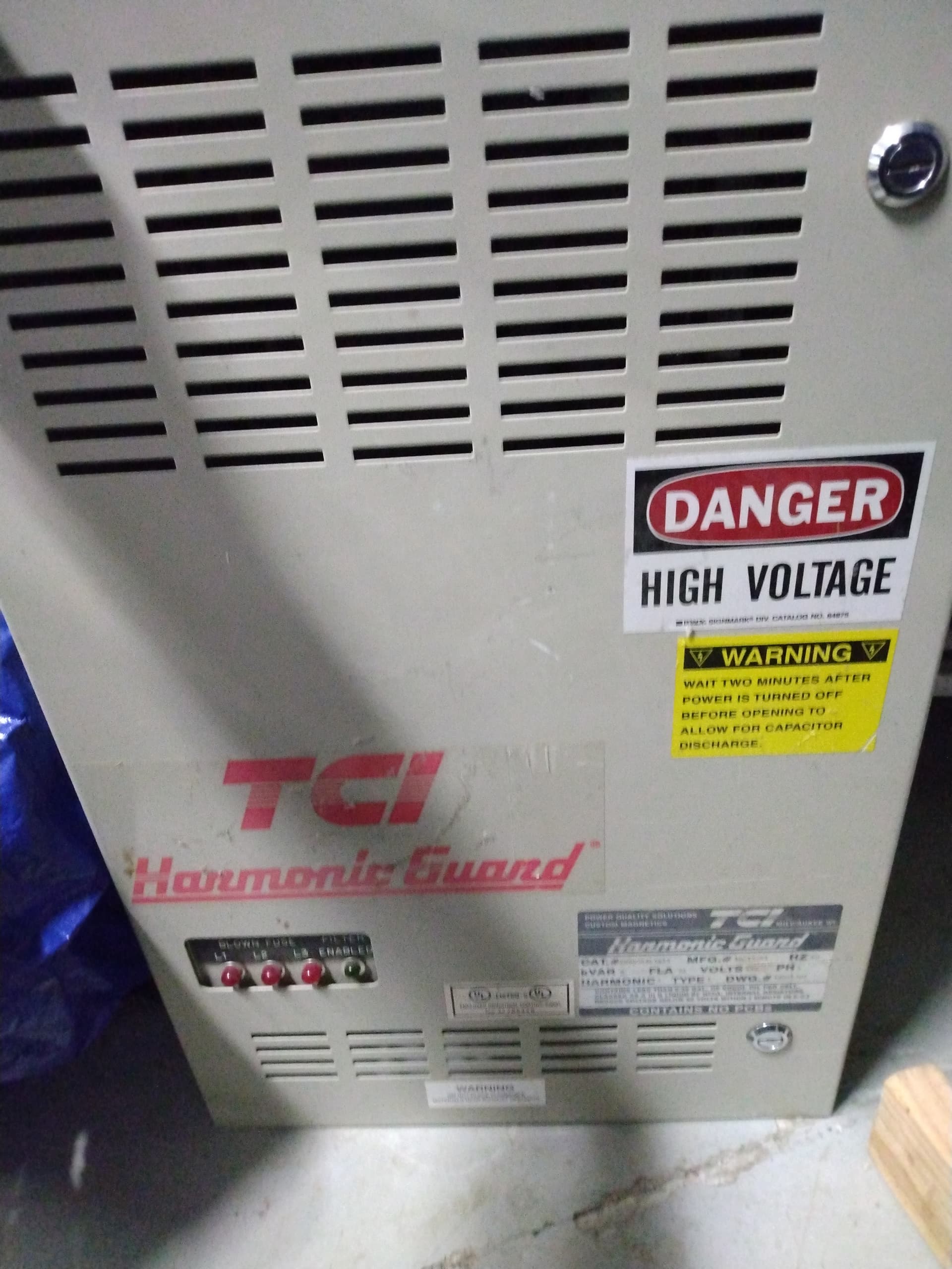
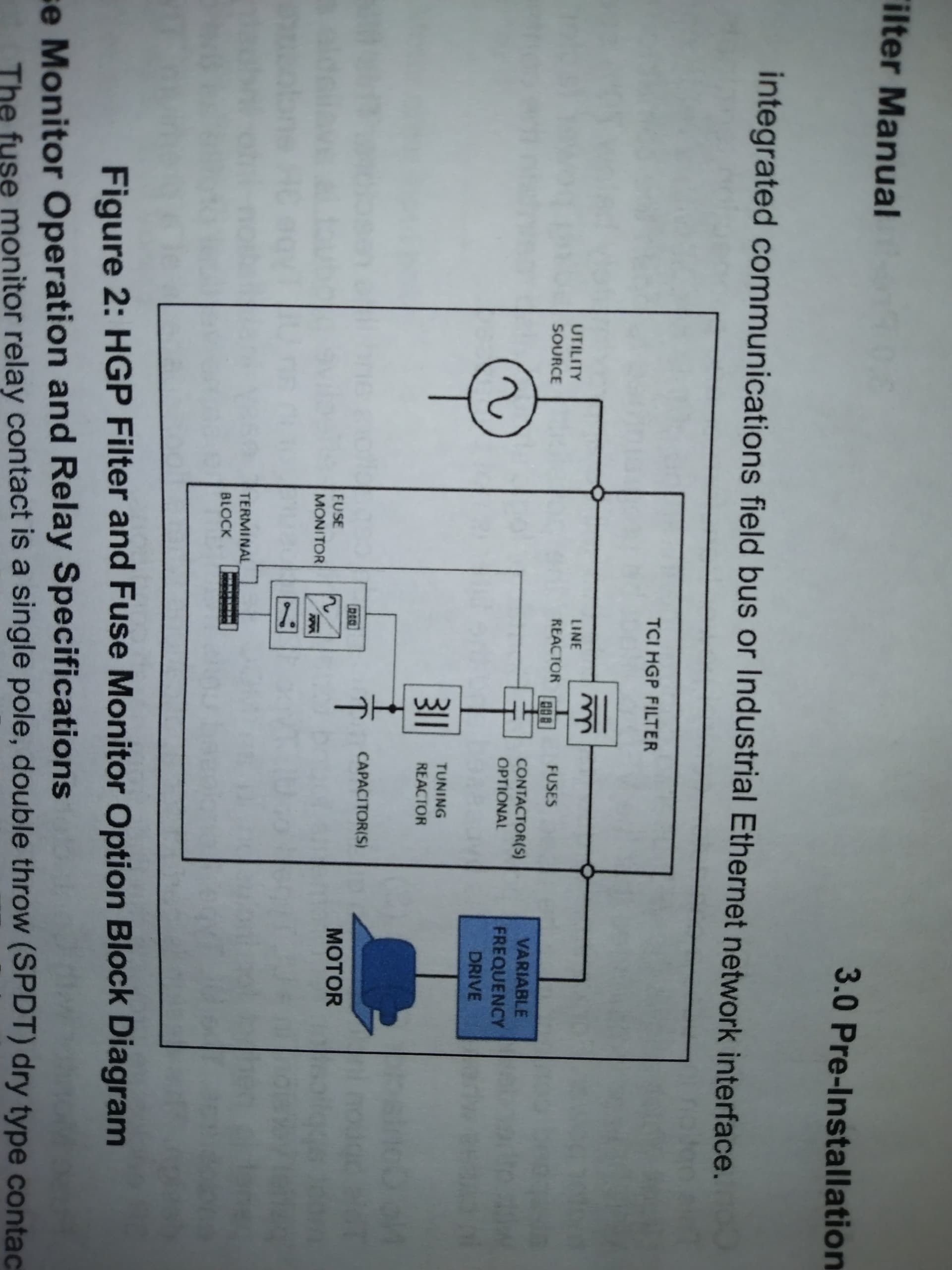
You familiar with harmonic filters?
No I’m not familiar what’s that? Like band pass filter?
Passive Harmonic Filters are currently the most common method used to control the flow of harmonic currents. T hey are built using a series of capacitors (capacitance) and reactors (inductance) forming an LC circuit in parallel with the power source. More complex designs may involve multiple LC circuits, some of which may also include a resistor. The passive harmonic filter is also referred to as a trap because it absorbs the harmonic current to which it is tuned.
Not sure if this would do anything to mitigate the overheating, one fell into my lap a few months ago and I’ve been trying to figure out how to utilize it. We have some weird power anomalies in the building we operate out of. Saw you mention harmonic losses and was hoping maybe you (or anyone reading) might have something to glean on them ![]()
Electric isn’t my forte
Electrical isn’t my strong suit either. I couldn’t tell you for sure if this would solve the issue of overheating.
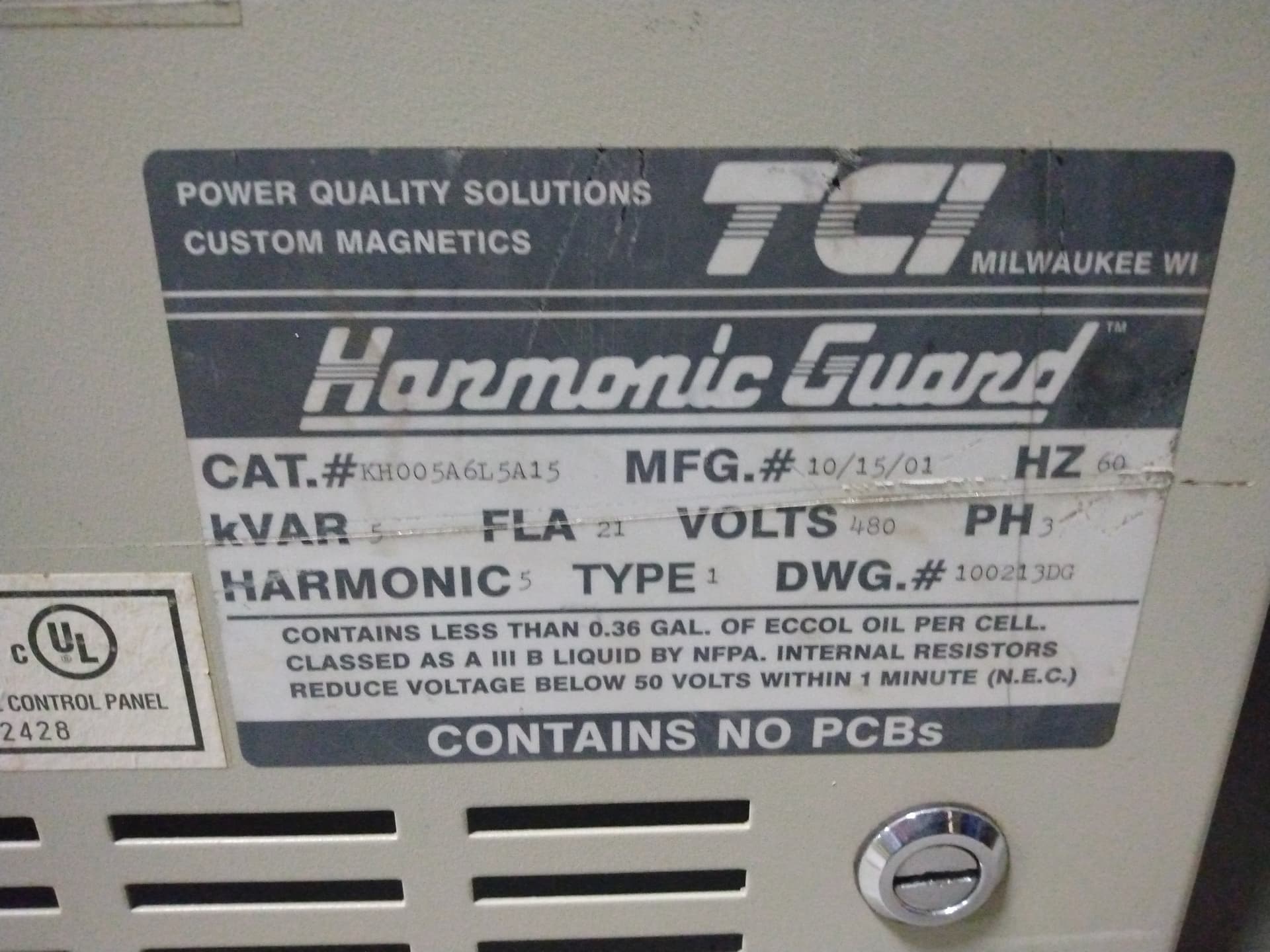
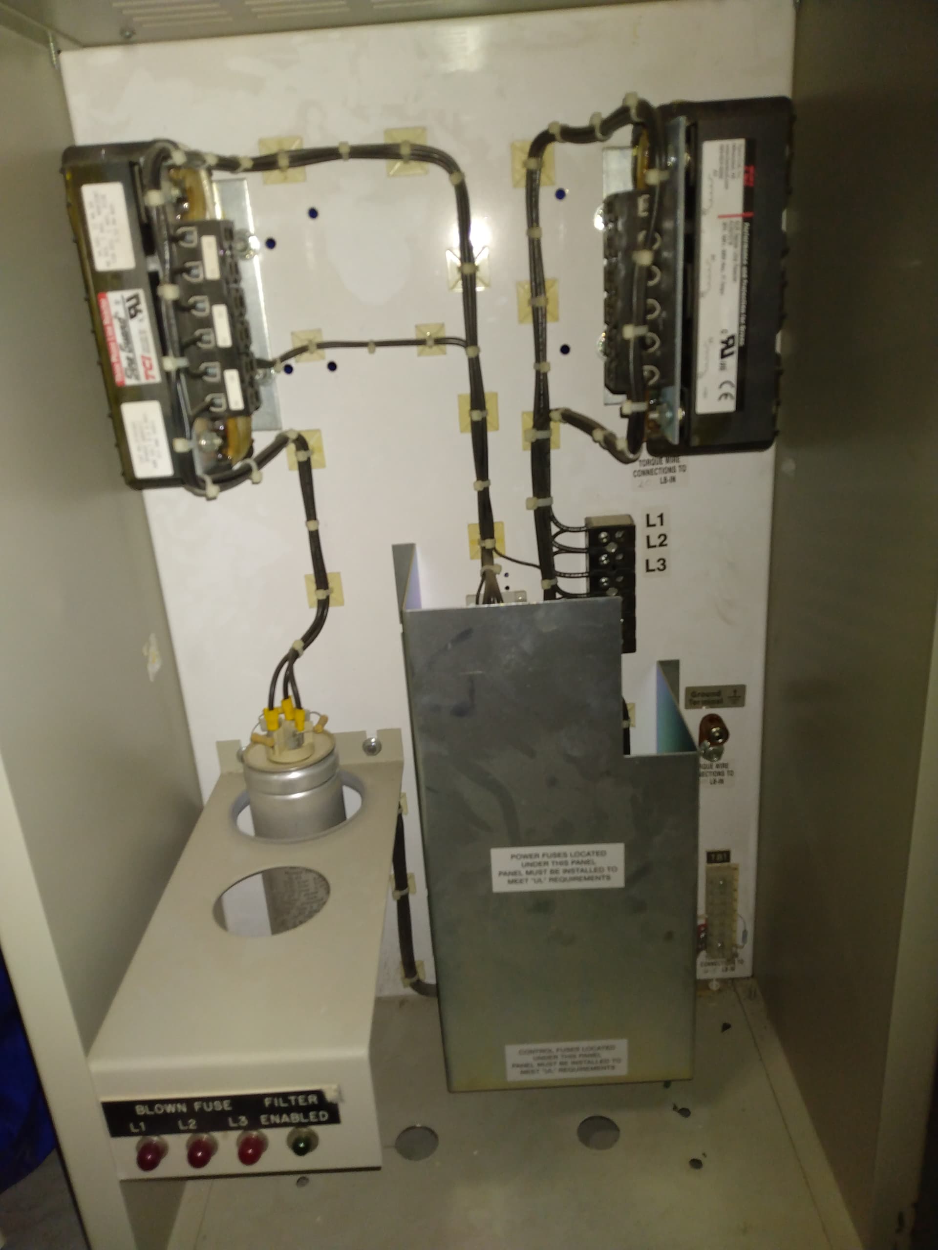
What’s the frequency range on the harmonic filter you’ve got? What’s the capacitor bank look like on it? You could use it to drive some transducers to rig up something with ultrasonics.
I don’t see a frequency range in the manual… I’ve looked through this thing a bunch of times and very little of it is clicking lol
You’re saying I could use this somehow with my bank of ultrasonic generators?
I was suggesting tearing it apart yo build an ultrasonic generator. Just forget that lol I forget that not everyone likes to jerry rig shit like me.
I was thinking, since it’s an inductor and capacitor in series the circuit already shares a lot in common with a drive circuit for an ultrasonic transducer. But I was expecting it to have a big capacitor bank.
These things are used to correct “dirty electricity”, have you had an electrician come out and measure the waveform and voltage variances coming out of your outlets? To at least confirm you’ve got dirty electricity.
No, I definitely enjoy doing that too… I love tinkering. Just wasn’t picking up on your line of thinking ![]()
The issue we have had a few times is VFD controllers being fried so that they will not work off external trigger voltage. Weird vacillations on the VFDs whirring until they can only work off the Run/Stop on the panel itself.
The building did a snapshot on the voltage variances and there were some weird spikes they said. This was 2 years ago at this point so any specifics were in one ear out the other. We’ve had a couple electricians look at it but no one is sure if the harmonic filter will do anything to help ![]()
I guess we haven’t spoken to the right electrician yet. It’s super rare that it’s ever an issue so we stopped banging our heads against the wall and worked out a couple mitigation protocols for when it does happen.