Thank you
To start, around half capacity on input. Around 125 L/H
Thank you for the reply…I do have a valve to shut off incoming tinture to FFE which makes sense but im fighting the exhaust side when it condenses and is pumped into the recovery tank. It builds up pressure in the recycle tank and causes the pump to get real loud and cavitates… I thought maybe these were closed loop systems to where after the return condensed etoh enters the tank that the exhaust would return back to vacuum to create a loop. Im thinking im wrong here. Perhaps the exhaust supposed to be vented to outside air after it reaches my storage tank? Excuse me with my ignorance on this but its the first FFE I’ve ran. Looking to start it without any surprises before I start the heat.
your vacuum on a FFE should be attached AFTER the condensing side, if you are maintaining a vapor/gas headspace upon the condensed solution layer.
EG, vacuum on a BizzyBee FFE is attached after the condensing section, and there are gear pumps that REMOVE the condensed liquid from the side that is filled.
I don’t want to piss any manufacturers off and potentially release IP that I understand that they may not want shared…
If you are using a collection vessel to pull vacuum off of, separate from your FFE condenser column main body, and expect thee KF/Stainless/Polymer hose connecting the two ‘vessels’ to flow BOTH a vapor/gas and the condensed solvent solution, you’re in for a nightmare maintaining vacuum /flow…
You will cause a vapor lock at times, and its not fun to have bottlenecks, when you’re expecting a constant throughput experience.
1 Like
I understand your situation now…
If your vacuum is attached BEFORE the recovery tank, and your recovery/solvent collection pump is a GEAR PUMP, you can likely open the collection tank to atmospheric pressure.
Most gear pumps are rated to operate under vacuum and will produce a vapor lock against vacuum, as long as the pump gears are slightly wetted.
1 Like
I am only using a liquid ring pump.
1 Like
Does your collection vessel not have a pump feeding it the collection solution?
Where does the vacuum attach in the system PID/Process Line?
Here is a photo of the pump and tank.
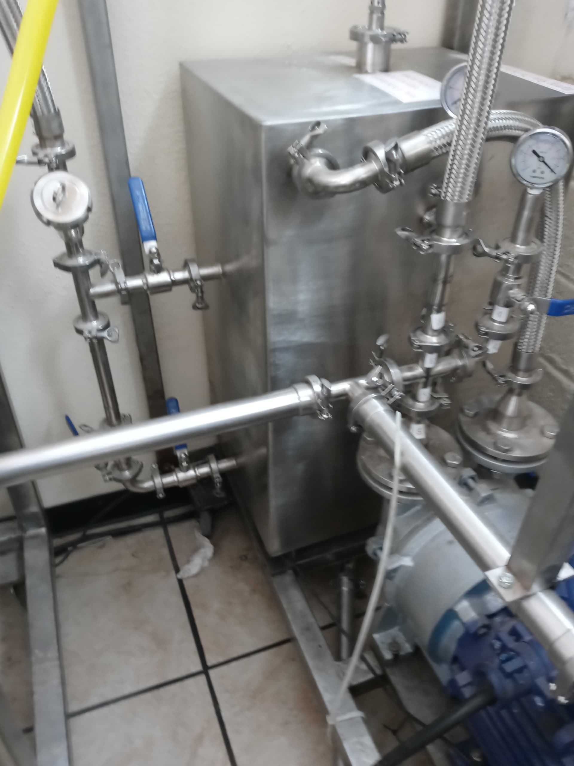
The pump vacuum has two spare ports as well for transferring fluid to tanks and centerfuge and then outlets into the top of the recycled tank.
Left side of pump is vacuum.
Left side of tank piping is the outlet to small condenser and then to storage tank.
1 Like
Where is the ‘pick-up’/inlet line for the flow from the collection tank, flowing through the ring vacuum?
Honestly looks built/hooked up incorrectly.
You need a gear pump to properly run the output flows on these units.
The ring pump will not suffice for all roles…
I am working on multiple china FFE projects right now, rebuilding client systems that were spec’d and built incorrectly.
You likely need a dedicated output pump for your solvent flow, in between the collection vessel.
That collection vessel should be scraped, tbh.
1 Like
The pickup line comes through the bottom of tank and connects to the center of the pump to create the liquid ring. I was under the impression that the exhaust that’s pumped into the tank would push alcohol down and out the left side of tank to the outlet that runs to my storage tank. No matter though if its pumped into the recovery tank or storage tank its still builds pressure after fluid us transferred as the pressure is trapped. So the problem I can’t figure out is where the exhaust goes. Outside air or vacummized back in ti system?
In operation mode the top valve on left is open and exhausts the recycled alcohol to storage tank. Once it transfers into storage tank the pushing pressure had to go somewhere.
Whoever sold you this doesn’t know how to run it lol…
You need a different system for the solvent collection.
Passive like that doesnt work. You need a gear pump.
Right now you aren’t going to do much with the vacuum acting as the pressure for the solvent collection vessel…
Unless the vessel is hydrolocked, and the inlets from the condenser side have one way valves, it wont work…
The collection vessel must be either a vaccum point, to force flow of solvent to the collection itself, or must use a gear pumo to transfer to the collection vessel.
2 Likes
Im sure of that…lol The reason im here. 
Ok. So if I got a gear pump for transfer, where would the exhaust of the regular running of the FFE still go?
Dm me is you wanna consult, I cant comment answers all night lol.
I’m probably able to fix that fairly easily, though.
2 Likes
Will do.
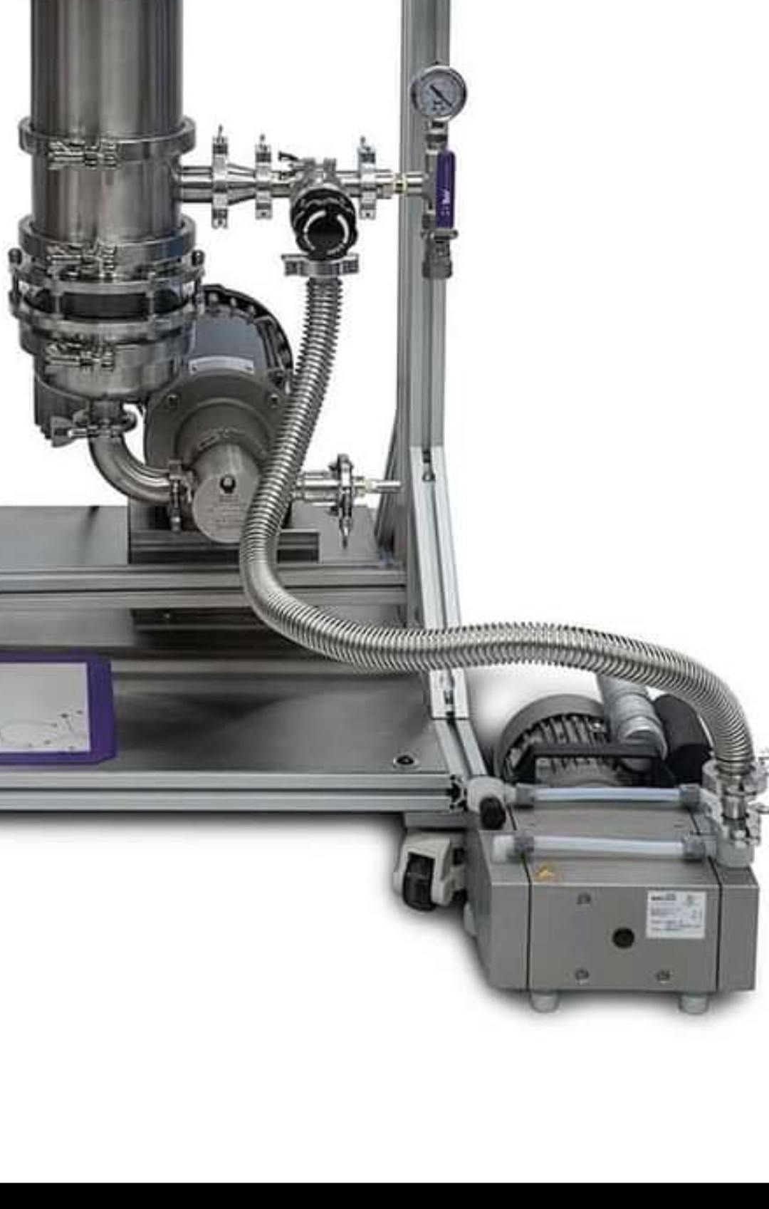
That pump looks like an awful lot like a welch diaphragm vac pump
2 Likes
Bvvs falling film is lowkey fucking brutal $ for $ and they know what they are doing.
BVV is the most humble and consistently solid company i have worked with and the fact that tjey just slid in a badass FFE without fanfare just makes me love em all the more
2 Likes
Thats because it is a welch pump.
They ain’t hiding it.
Welch makes badass pumps, they are of quality.
They’re honest.
2 Likes
Just putting up how they setup their manifold.
Could possibly help op with the configuration.
1 Like