There are quite a few on here who are using light controllers to power their grow lights and other things in the room. There’s a bit of info out there on making a DIY controller, and a lot of info on how unsafe most of the controllers are out there. I figured this would be a good place to discuss building your own.
The writer has 4 plugs connected to their relay. They state to use a power strip for each plug so you can trip the fuse on the strip if you have a ballast go out and more current is drawn for that device.
Is it overkill to wire up a small sub panel with breakers on each line? I understand it would be more wiring, but would give you much more peace of mind if things went wrong. This would be something like: Panel > Controller > Sub Panel > 4 Breakers (1 outlet per breaker) > Ballasts
What would be the best way to protect the circuit between the controller and the ballasts? Using a power strip to me seems like a hacky way to go, but might work fine given the low load on the system. A sub panel seems overkill, but may be the best way to go. Any options in the middle?
This is almost exactly how I design all of my lighting controllers. Rather than running power from a main panel to the controller to a sub panel, I start with a sub panel with plenty of capacity for the number of lights being controlled and use a HWH timer to fire all the contactors at once. Most everything I do is 277v so it’s usually three 1000w lights per contactor bank per 20a 277v breaker.
So you’re usually running 3 lights per relay? Is there any concern with running multiple ballasts per controller without any additional fuses/breakers between the relay and ballast? I’m a bit worried about if one were to go out, would more power be sent to the other 2, or does that just balance itself out based on the draw from each remaining ballast?
The thread I linked stated to use power strips to protect the ballast if this were to happen, but I’m not quite following how it would cause damage to the other devices anyway if one went out… In my understanding, the relay is pulling whatever devices it’s connected to are requesting right?
So say I had 3 ballasts pulling 5A each, the relay would be pulling 15A when all are running. One goes out, it would only pull 10A?
Just trying to understand the theory behind this better. I’m pretty good with electric circuits in general but there’s always room for improvement.
Think of it like a normal house circuit. The contactor is simply the light switch (capable of handling the required amperage). If one light bulb goes out, the rest are still fine. The receptacles are providing a set voltage, either 120 or 240 where I am and the device defines the draw in amperage. Your example is correct.
I will take a couple pics tomorrow of my 10kw controller. It’s very simple when you see it.
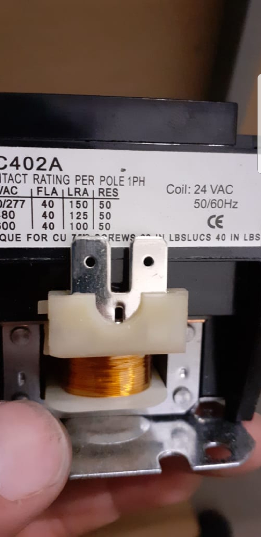
That’s the heart of the controller. It triggers on and off cycling. Depending on amp load, determines controller amp. Most 4 plug controllers use a 30a contact. 6 plug use 40a, and so on.
Good points. I always turn the main off to the panel before doing anything. Once I’m done I turn the main off with the circuit I’m working on off, then turn that breaker on and test it with a volt meter to ensure it’s working as intended.
I should be well under the 80% limit with this setup. The ballasts state they only pull 1.9A max, so I’ll be under 8A on a 30A line. I have 2 more 15A going into the room for the fans. Not running AC or heaters or anything.
I’ve wired tons of sub panels with integral controls for lighting, fans, co2… just make sure that you have the proper coil voltage for the contractor, and make sure the contacts are rated for the current/voltage they will be switching, use a time clock, or a programmable relay to run the contactor. I usually have boxes of Allen bradly contractors sitting around from control demo jobs.
quick wiring question for the gurus… If i’m running a new 220v line from the panel to the room I could run a 3 wire setup, but ideally I want to run a 4 wire for added safety since code requires that on new construction anyway… I’ve done some 3 wire 220v circuits before, a couple of 4 wire circuits to outlets, but those were always straightforward. 4 wires, 4 ports etc.
The 3 wire config makes sense since the DPST relay only has 2 ports on it… If I were to go 4 wire, where would the 3rd wire go on the relay?
3 wire: Black/Red > Relay, White > Ground
4 wire: Black/Red > Relay, Ground > Ground, White > ?
Does the white on the 4 wire setup just tie into the neutral on the outlet lines?
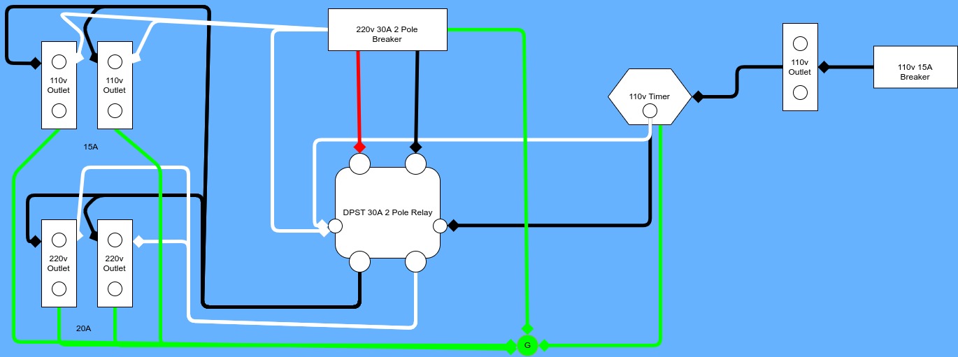
EDIT: My question might make some more sense with a diagram. How does this look for wiring everything up? I thought about adding some 110v outlets onto the circuit so I can plug a couple of fans into there so they can turn on/off with the lights.
Zthe Neutral is only used if 120v is needed to be derived from a 240 single phase circuit. The 240v breaker that supplies the lighting contactor power is the overload protection for the lighting circuit, if it is a 240v circuit the neutral is not required. It’s a bad idea to put 120 loads on a 240v circuit in the manner your proposing as you can easily have to much draw on one half of the 240 phase over the other. You would be better off using a separate 120 circuit controlled by the same timer.
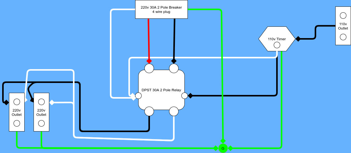
good points, safety is the top priority. If I just run the 220 circuit in the controller, you’re saying I don’t need the white wire wired to anything, just the 2 powers and ground? I’ll be using a 4 prong dryer outlet for the main supply to the controller.
Hook the dryer outlet up 4wire as it should be, if your using a pre-made dryer cord just cap the neutral Wire from the cord in the lighting contractor, it is not needed. If your buying a cord end that you intend on attaching a 3wire cable to make your wip, just disregard the terminal that the neutral wire would normally be connected to.
I finally got around to assembling the unit. I forgot about leaving the dryer plug neutral wire disconnected and had it hooked up to the neutral for the 110v coil trigger. When I plugged it in the first time it blew the 110 breaker. Would that be because I hooked up that neutral when you said it should be not connected to anything?
This is my wiring currently. @that445guy mentioned to leave the neutral disconnected in the controller box. I didn’t do that and had it wired up to the coil triggers white wire and am wondering if that’s the cause of the pop. I’m not seeing anywhere that I could have a ground going to a hot here
Yes, for 220v the neutral is not necessary. Is your contactor a 24v, 110v or 220v coil? You should have 2 legs from your source 110v each. These run thru your contactor then on to what you are trying to power. The contactor has two legs on either side this is for the coil supply. Thia is a 24v coil contactor.