Wow he simply gave an example of how it works from piecing parts together. Wether those pieces are custom fab or just meticulously ordered to fit perfectly together.
He showed a solution and seemed proud of his work. Why knock a guy trying to show us a way. May not be the only way to do it but it works for him…
I would say the vast majority of us havent. U sound like a miserable teacher who doesnt want his students to ask questions and just read the book. “Did u read the whole book? No? Then we cant talk about it”
I personally have not worked on putting a machine together this elaborate but the way i see it, i would prpbably want to put a ball valve after the gear pump, so that the gear pump isnt feeling any stress?
Kotk was nice for sharing how he did. I wish we could demystify this once and for all. I want to build these for myself but don’t have the pesos to r&d all these pumps I’m seeing so any true info helps. Moving pictures are a great bonus!
They are used in a variety of industries, plastic injection molding, chemical synthesis as dising/flor pumps, oil and gas as feed pumps, etc…
A similar style pump, lobe pumps, are NOT made for vacuum use, but can handle more chunky consistency products. Lobes are use for food and beverage industries, almost every processed food you eat is produced using lobe pumps.
Gear pumps by their design tolerances are MADE to operate under vacuum.
The tolerance of the head dictates the vacuum level the head is capable of being pulled down to, to feed towards, or pull out of.
Lots of the pump heads @Kingofthekush420 posted he uses are NOT made to withstand high vacuum levels. Like stated, the precision of the gear pump mechanism dictates the level of vacuum ability they can feed from and pull out of, WITHOUT needing check valves.
You don’t necessarily need check valves, or even gear pumps for a WFE.
You can use a needle style PTFE valve to control the I let flow, and use your vacuum levels to control the inlet flow to a WFE.
Most of the stills I used in my organic/Inorganic labs in college did not have checkvalves or gear pumps. They are unnecessary. Unless you start wanting to feed at a very high speed, or work with a substance that is highly viscous even when heated.
Having a ptfe needle valve does not seem that precise…
Why settle for something u have to get in the perfect rotation everytime when u can just press a red button and everything flows the way u want?
If the gear pumps were perfect then yes we wouldnt need a check valve but almost all the times ive seen gear pumps used from summit brand to B&W brand, they all needed a check valve eventually.
So yeah maybe a 50k gear pump would work perfect but i think most of us will settle with an imperfect (sub $3k) gear pump that just needs a check valve or ball valve to function properly
Just put your check valve in a place that is 1) easy to replace, ideally with a valve upstream so when it needs service its easy to swap. 2) have 2 or 3 checks on hand. you might not see any issues for a yr, or could see issues in 2 weeks. 3) Liquid column with “goose neck” is your friend (although this has been debated) Height of such isnt trivial and i think theres benefit to having a smaller discharge nozzle ID than the tubing. Continuous discharge from high vac is a difficult app and aint nothing wrong with redundancy, im a believer in “the little things add up” (for better or worse )
Def could design your own if ya got the time. the industry needs a check for this app specifically. At the very least it does make for a simpler startup/shutdown i guess. (might could instead use a flow sensor and solenoid thats spec’d to temps)
I think the best check would have the following characteristics - 1) minimal volume and deadspaces. 2) easy to heat uniformly 3) drainable 4)easy to service (seals and mechanism) 5)…thoughts? i know im missing something here
You have a line to give them feedback on their gear pumps? Because whoever designed their stainless rotating shaft that goes inside not one but two stainless plates, in an environment that withstands tremendous thermal cycles and no bearing/bushing to speak of can suck my ass
I would think for deep vacuum you would want an actuated ball or globe valve. IMO, most check valves don’t seal well enough to hold micron vacuum, regardless of soft seals. I also don’t see gear pumps holding hard vacuum while not running. Especially if they operate at a range of temperatures (if the seal tightly at room temp, wouldn’t they bind at elevated temp?). I’ve personally worked with a ton of deep vacuum equipment but never had a chance to use a gear pump as a positive shutoff
Companies need their noses rubbed in their own shit until they stop doing stupid stuff and selling it at a premium. Putting a rotating shaft inside a metal plate, both made out of a metal known for galling is a recipe for failure.
Don’t know if I’ve got any pics of the failure but I’ve repaired at least a dozen of these pumps and ones clearly very similar or inspired by the yhchem ones all with the exact same failure, always galls on the stainless shaft inside of the stainless plate. A brass or bronze sacrificial bearing/bushing would keep this from happening if the OEM knew WTF they were doing
Hi , great post here. Any chance you can DM me with some of the parts you have had success with. We are trying to build a feed system and two discharge pumps. Happy to pay for your help with this since you already went through the pain of putting it together.
I went ahead and gave this a shot, feed and discharge pumps are almost a necessity to turn around oil in a reasonable amount of time in a wiper; though I put them in the quality-of-life category due to their expense.
The Diener pump (@MedicineManHempCo posted) is ok, they are hermetically sealed and driven with a magnetic drive. This is good from a sanitation standpoint as there is no contamination to be worry about, but if you oil is not heated enough, the pump will slips as the torque required to pump is much too high for the magnetic coupling. This is especially an issue with crude/ tails that begin to get glassy.
@Kingofthekush420 has a direct drive style pump head that is better for this issue. However, I’m not sure how I feed about this since any motor shaft that is in contact with food generally needs to maintain a constant positive pressure to expel a small quantity if fluid so particulate generated from shaft abrasion doesn’t contaminate product. Since the still body is below atmospheric pressure, there runs the risk of air forcing this particulate into the oil stream.
Another issue I have with this is speed control and feed calibration. The dc motor that comes with the pump head is WAY too fast for this (a few thousand rpm), 60 rpm motor is the max needed for 2l/hr. The pumps displacement (0.6ml/rotation) and that is still a bit much. I am currently controlling the speed of a DC gearbox motor with a PWM controller that is fed with 12V DC. Even at 50% this is too fast and I flood my still if not careful. This is likely due to the air pressure casuing the fluid to flow much faster through the system so pulling a vac on the chamber could help. There is a big limitation with this simple solution: DC motors lose torque below 40% duty cycle so there is a very small effective range between too low to pump and pumping waaay too much feed.
Today, I have a stepper motor coming, with the right controls, this should have a much larger range of precise control while still maintaining torque.
The final thing is the requirement for some kind of valve to shut off flow during pumpdown. Once the pumps are primed, a small amount of oil stays entrained in the pump head, sealing it from leaks. However, if material in the feed runs out, air will make its way through the teeth of the gears and you will see several thousand micron. I’m going to try a simple valve, but if needed for discharge, I plan on using a yor-lok check valve to just slow down the leak rate.
Hope that helps and if anyone else has tried this for a slightly smaller scale than @Kingofthekush420 ‘s insane 30L per hour I’d be curious to hear if any other attempts have been made.
For the speed issue, I believe another solution would be to source/select a motor that you can pair with a transmission to get to your desired gear reduction ratio to match your processing speed. (I have only used bldc and magdrive I like them both)
I run check valves wrapped with heat tape, I also have a low side (drainage/shutdown) and high side ball valves for startup(pumpdown).
Another thing that might be helpful is I have found setups equipped with 3/8” ports to be much more resilient then 1/4” which also does work great, but requires more care in shutdown procedures or more cleaning.
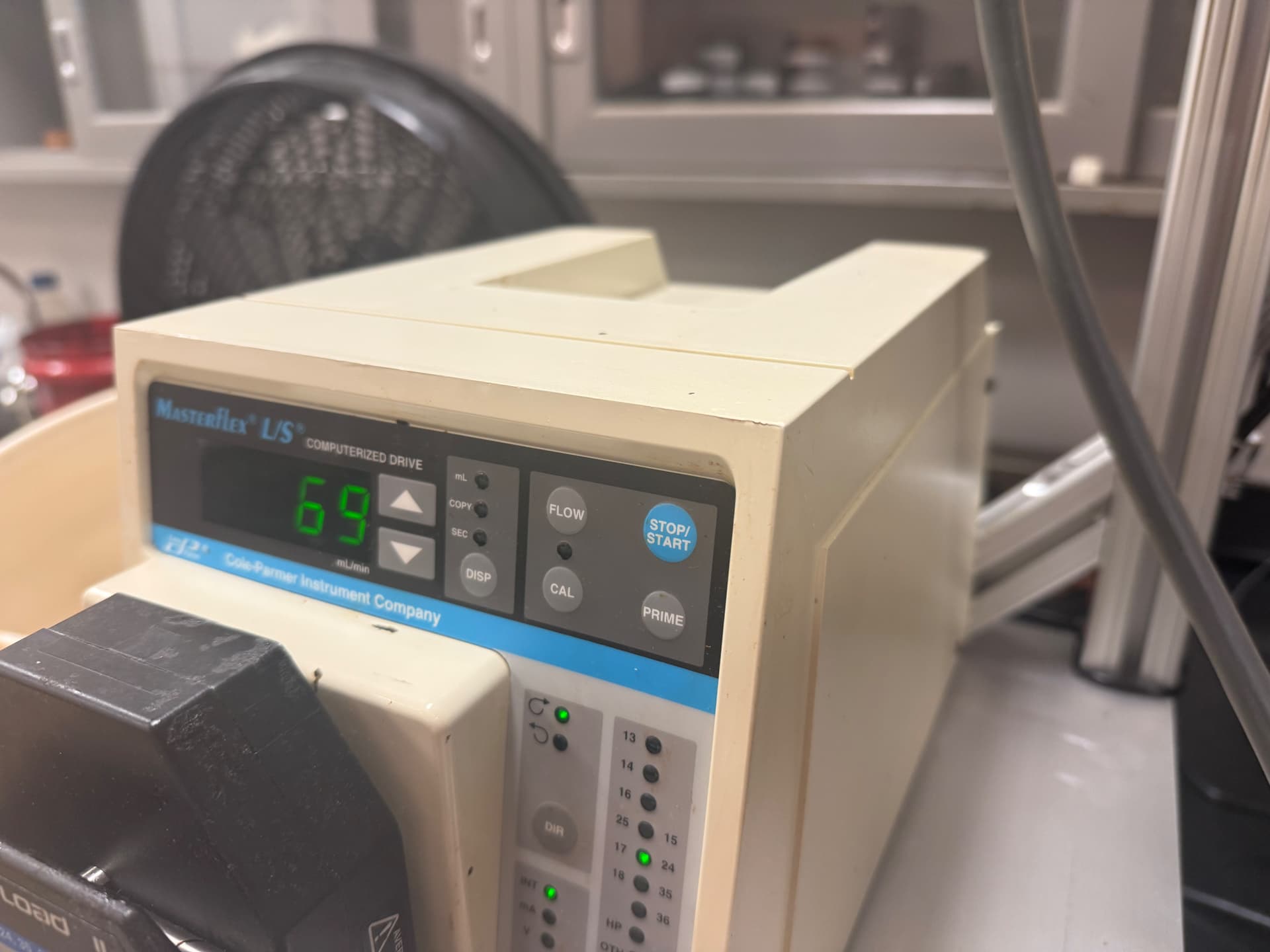
I still feed with Peristaltic pumps myself.
Peep my vintage masterflex.
I have a masterflex I picked up but I have never been able to get crude to flow through it. I also don’t think I got the right tubing so that is another part of it, but I’m unsure why I was never able to get it to work.
I found these resources to be helpful for buying tubing sizes that match up with my target speeds. As well as sourcing alternative tubing types.
The pump heads are supposed to be paired with specific tubing or you’ll see more pinches and pops. Its shows more details in the pumphead selection guide I linked. I will dm you my tubing recommendation, I like it better than the old stuff.
I do a daily shimmy and slightly to adjust the hose, it prevents it from becoming a vac’d into a rubber band and extends the tubing life. I also use stainless dipsticks with hose barbs to cut down on tubing usage when applicable.
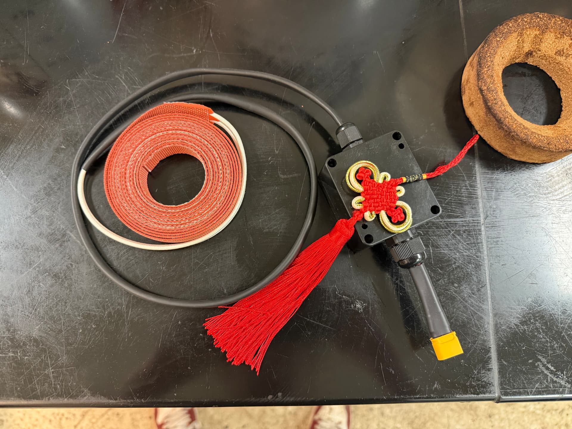
I haven’t used my keenovo tape yet, but I did really appreciate the +4 luck charm.
Makes sense I noticed flat spots, thank you again.
I like your heat tape, I went with a cart farm since it had everything in it, controller and tape, I’m still not very good with electronics yet. Trying to get better but I can copy a wiring schematic well enough.
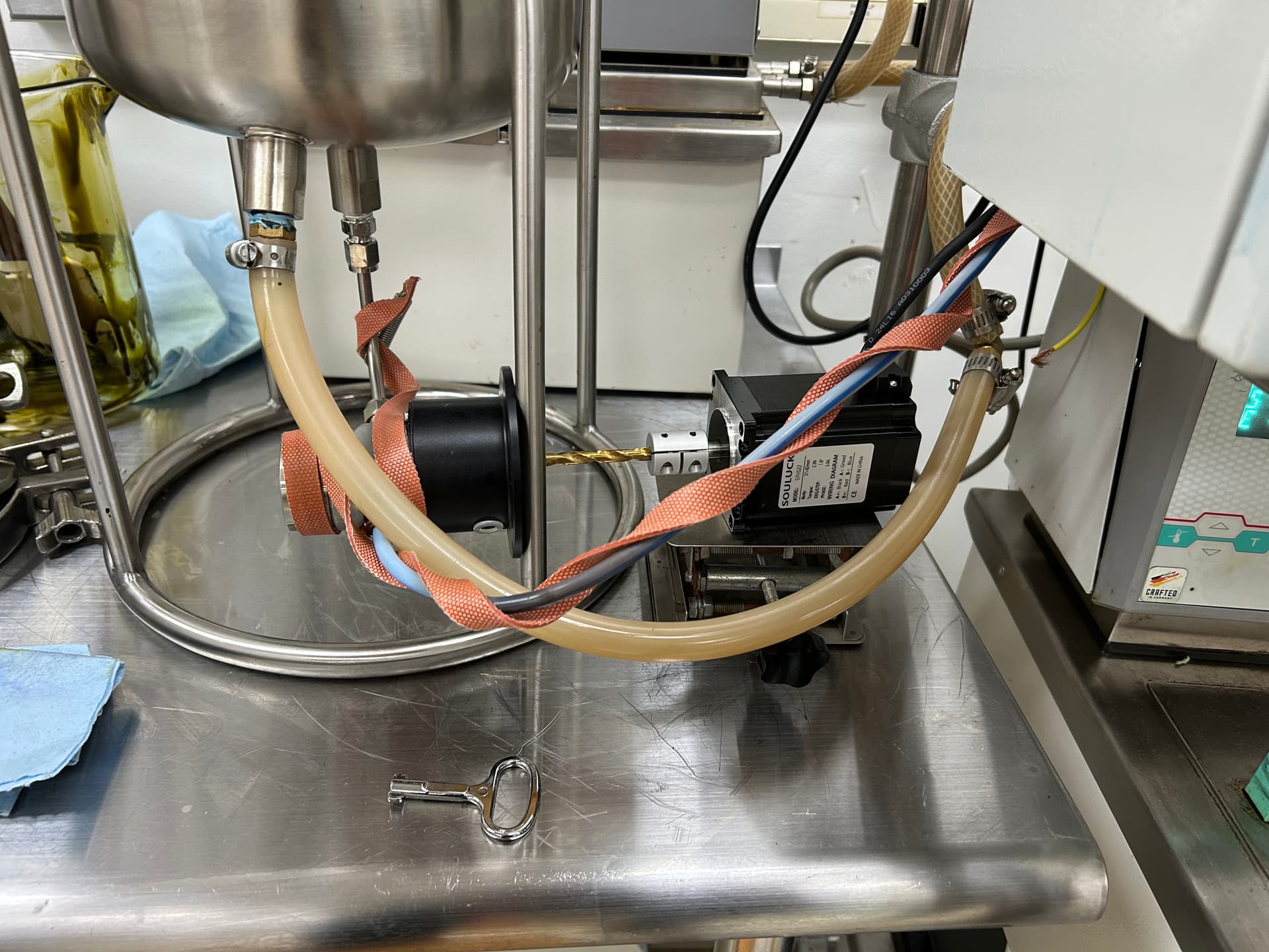
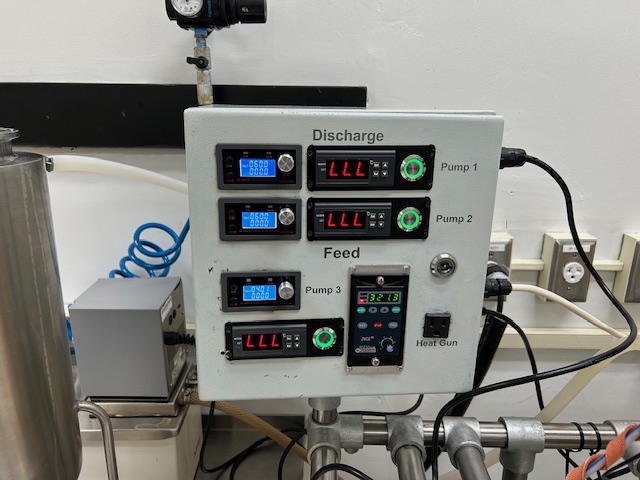
I’m proud of the current build though, 3 controllers and 3 segments of heat tape, controllers, 3 motors and pump heads, I think this will come out to $1000-$1200.
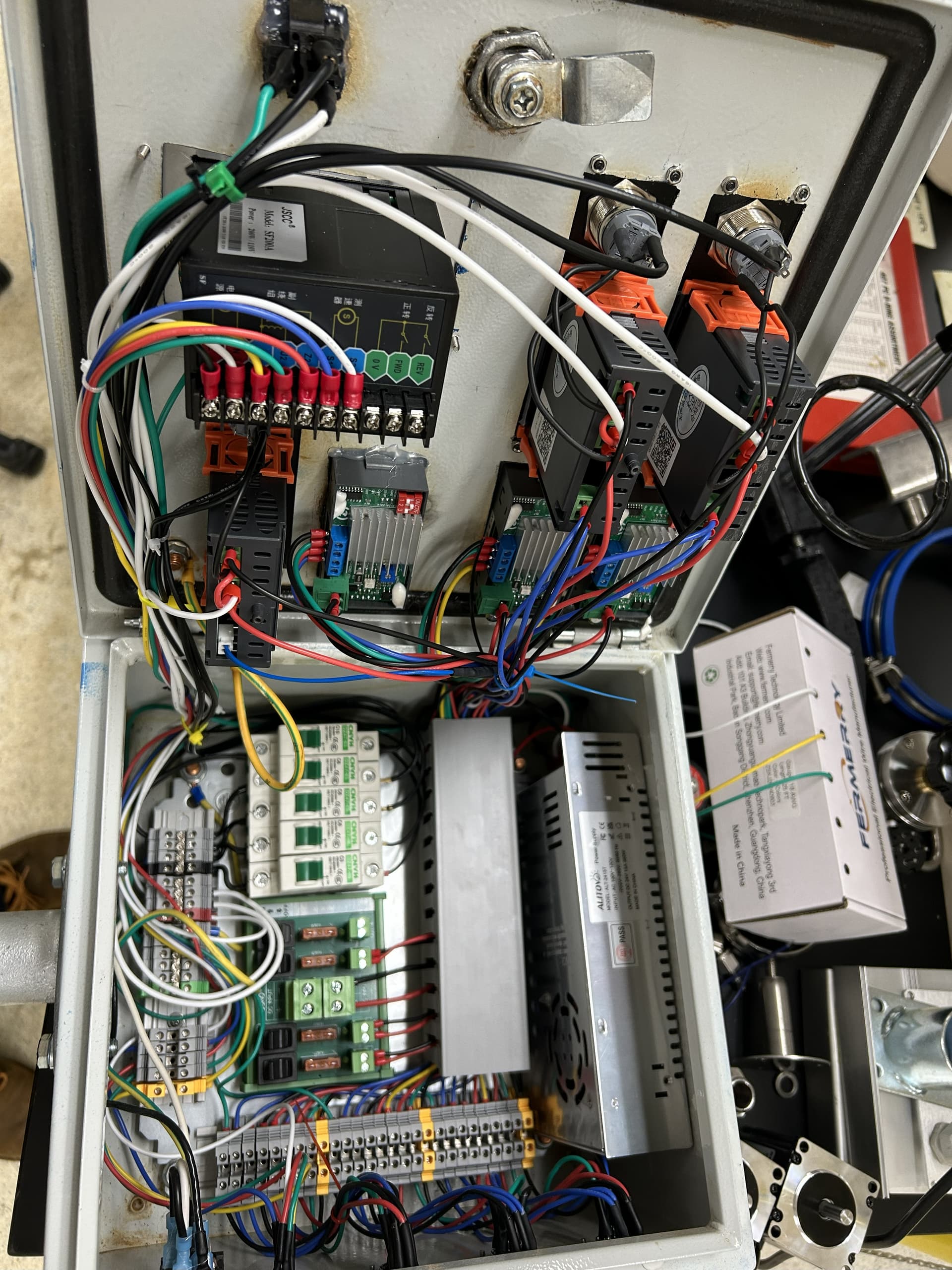
A few weeks, a mountain of parts and 30hrs of wiring later. This was the result. Lots of tweaks to get the hardware to behave, but was well worth the result.
I was a little concerned about these pumps handling residue, it can struggle on the discharge side, but getting it hot for squeezing out the last of the noids still functions works well for the feed. Good heat tape and insulation should help
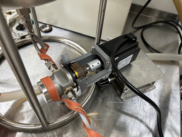
The stepper motor is the highlight for this project. I had struggled to get good sensitivity and repeatability out of a PWM controller and a DC gearbox motor. Upon calibrating this pumphead, the displacement was 0.6 mL per rotation. This means that a meager 60 rpm can pump 2L per hr. This is ludicrously fast and it’s always hard to know exactly how much is being fed with an analog dial and was between a flood and a trickle. The stepper is a great solution for this, and while a bit big for the torque required here, it was a $25 component so overbuilding didn’t hurt that bad. With the cheap controller I got, I have a feed resolution of 36mL/hr with a range of 3.6 to 36000 rpm.
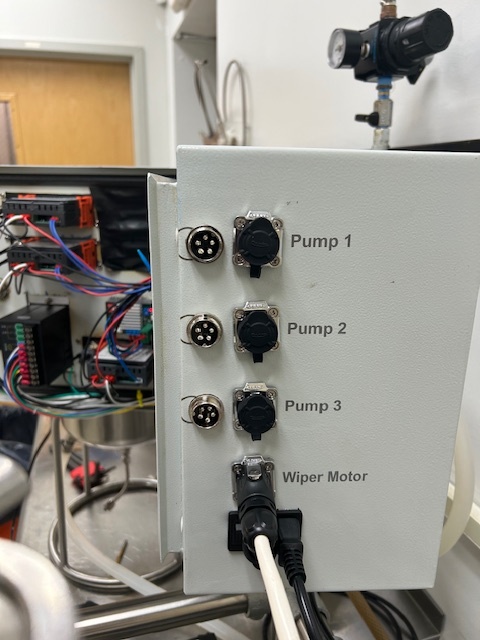
The other obvious positive is the quality of the electrical enclosure and wiring. DIN rails make this all look good, and despite this not being my first panel, I never seem to get one that is big enough. Just barely everything fit; bonus points for laser engraving the labels, and bonus points lost for mislocating them the first time on the side. The PIN connecters make maintenance a breeze. This is a Toption wiper and dislike how the wiper motor was hard wired because the wire was too short to set the blades on the spill pan. Now I can wash the blades in the sink.
The only drawback is the low torque of the pump head due to the magnetic coupling that is intrinsic to the gambro. I have a direct drive gear pump that still needs to couple to a motor, but it is quite large for my purposes. It’s unnecessary for runs where residue can be contained by a 5kg flask, but above a certain size, it’s necessary.
Overall, I’m quite happy with the result. The enclosure, 3 pumps, 3 heat tape controller/lengths and most of the plumbing (valves and fittings) came out to $1200. Hard to beat that result when one pump head and motor run $4000 and up.
Edit: If anyone wants a more detailed build info, shoot me a dm.