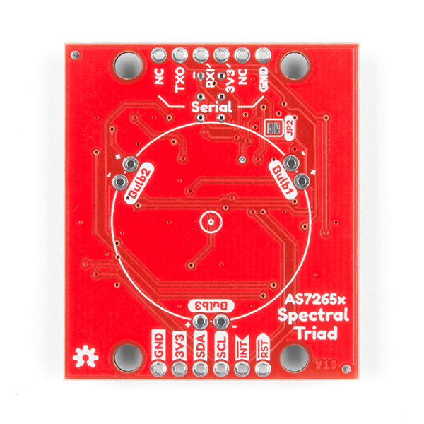
If you don’t solder the sparkfun one is the better choice because you have the qwiic connectors and such plus the ir and uv leds are on board already like @blackie said.
F-ME, see @CBNight, told you i always f ish up. I gotta buy one of those sparkfun boards. damnit. I have two of these pesky boards if any one finds themselves needing them…
Probably not. I wouldn’t get my hopes up, but it would be interesting to see what happens when you test different potency stuff.
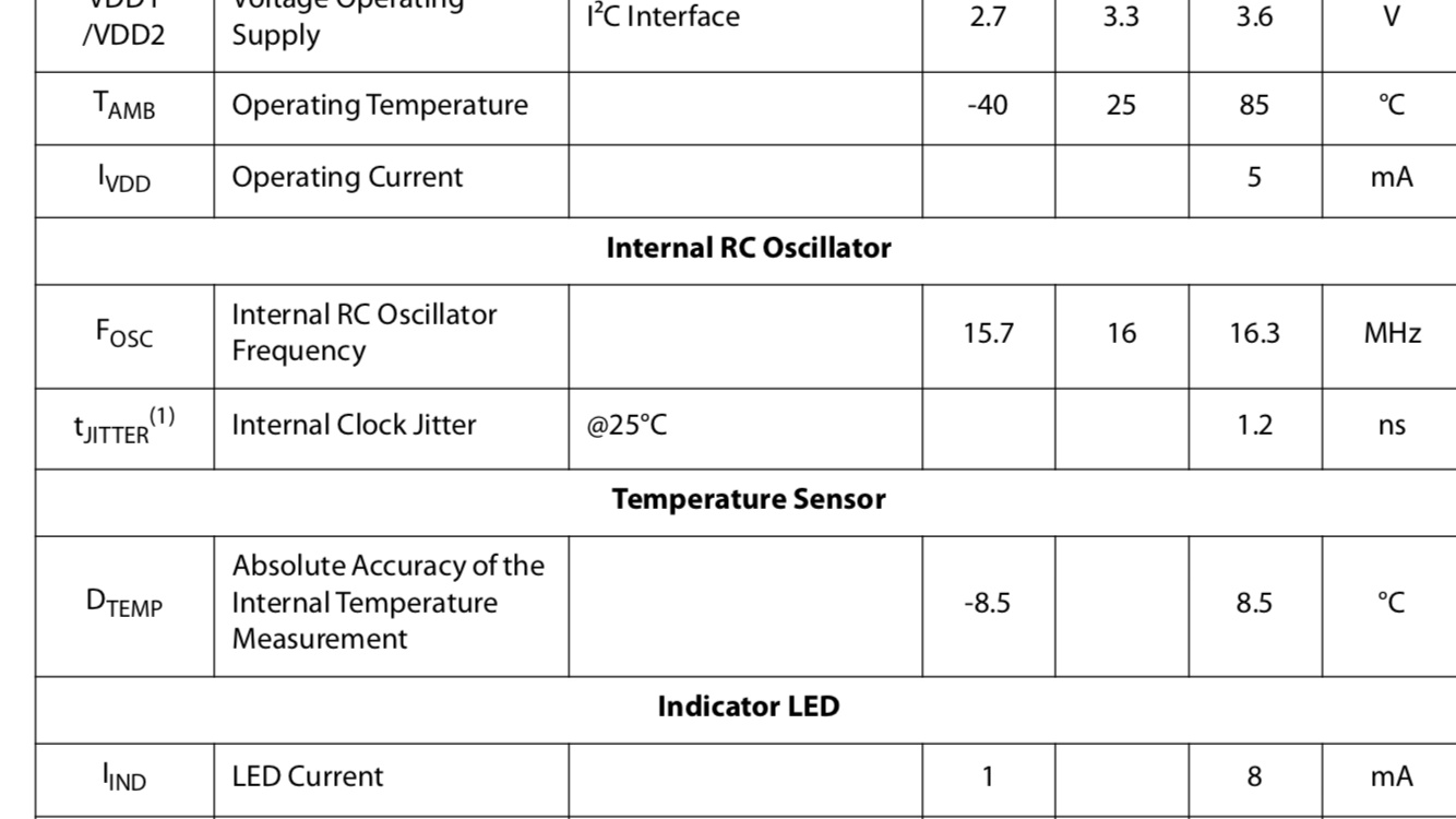
The accuracy on some of the channels are +/-12%.
I was monitoring the sensor temperature in real time, and noticed it bouncing around. Turns out it is only accurate +/-8.5 C. And the sensor is using that reading for temperature compensation calculations.
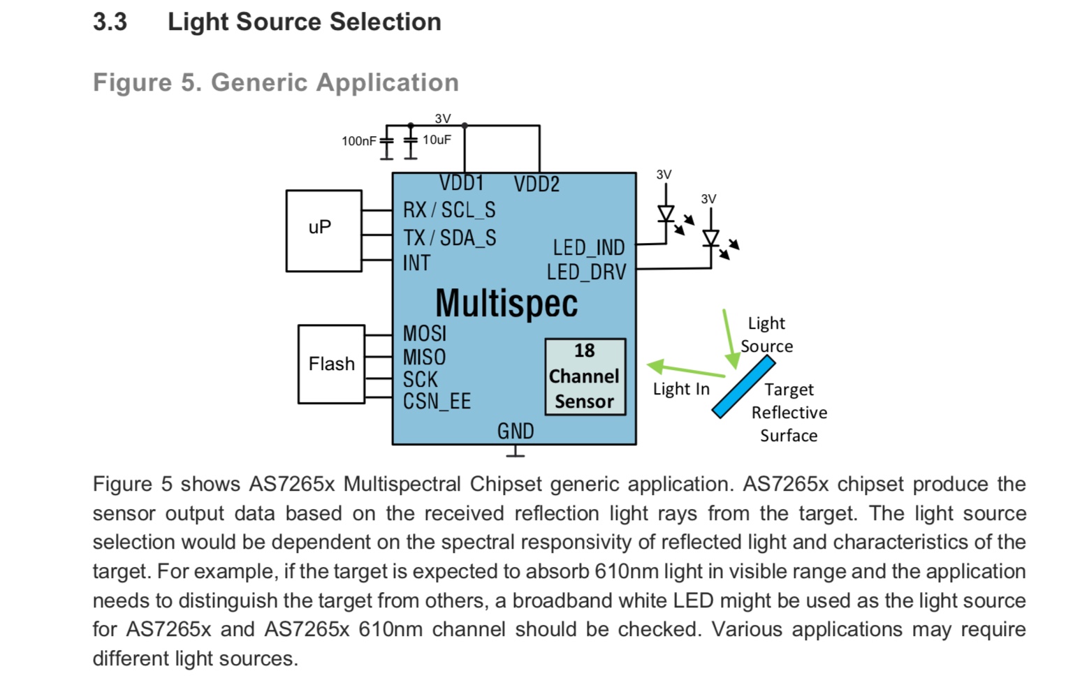
Each as7265x chip has two LED drivers. The pesky products board only makes use of one on each chip. The spark fun board has a place to connect 3 additional LEDs for an off board light source, in addition to the three already on the board.
Got it working with the raspi. Arduino plugged into the USB port of the the raspi.
In my case the python script needed to be edited in order to point the serial port at “/dev/ttyUSB0”
also needed to lower the resolution from 10000 down to 1000 to make updates happen faster.
I am using python 3, and got an error about byte needing to be an str, or something. I had to change pySpectralTriadColoredScatterLog.py line 99 from
spectreList = spectreString.split(“,”)
to
spectreList = spectreString.decode().split(“,”)
there were a bunch of python dependencies. I just ran the python script till it gave me an error, then installed what it said was missing until everything was installed.
import serial
import numpy as np
import matplotlib.pyplot as plt
import matplotlib.colors
from drawnow import *
from serial import Serial
from scipy.interpolate import interp1d, InterpolatedUnivariateSpline
from math import log10
Ran into an issue where the graph doesn’t seem to be updating in real time.
It looks like the issue is caused by the Arduino constantly sending data over the serial connection. The raspi grabs some data from the serial buffer and graphs it, but the Arduino sends data faster than the raspi can graph it. The serial buffer gets fuller and fuller, and the graph doesn’t appear to update in real time.
If I kill the python script and restart, I get a good graph at first.
I fixed the issue by inserting a delay on the Arduino side so it only sends data every 10 seconds. Could probably do 5 or 6 seconds with my set up, but I am staying safe with 10.
I decided to order a raspi 4. I think I am currently using a raspi 2 for this project and it could use more horsepower. Shipping is $5 from this place, $40 total shipped