The combo, Kill-A-Watt meter → Auber DSPR1 power regulator with solid state relay → Auber SYL-1512A PID or ON/OFF or Limit controller with mechanical relay and K thermocouple → heater of a water distiller works fine. Smoother and more precise power regulation (watts) than with the Variac combo, but lacks the ability to 30% over volt available with the Variac.
It occurs to me that if you wired the temp controller and rotary encoder power controller as a single unit you could eliminate the mechanical relay. One of the wires from the power controller leading to the solid state relay is run through the internal relay contacts of the temp controller.
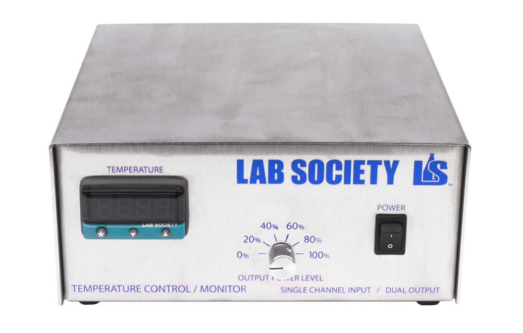
I see Lab Society has a controller with a dial reading % power regulation and PID control, $1,300:
When you dial in the power (watts) you don’t need full PID function, ON/OFF works just fine without over/undershoot.
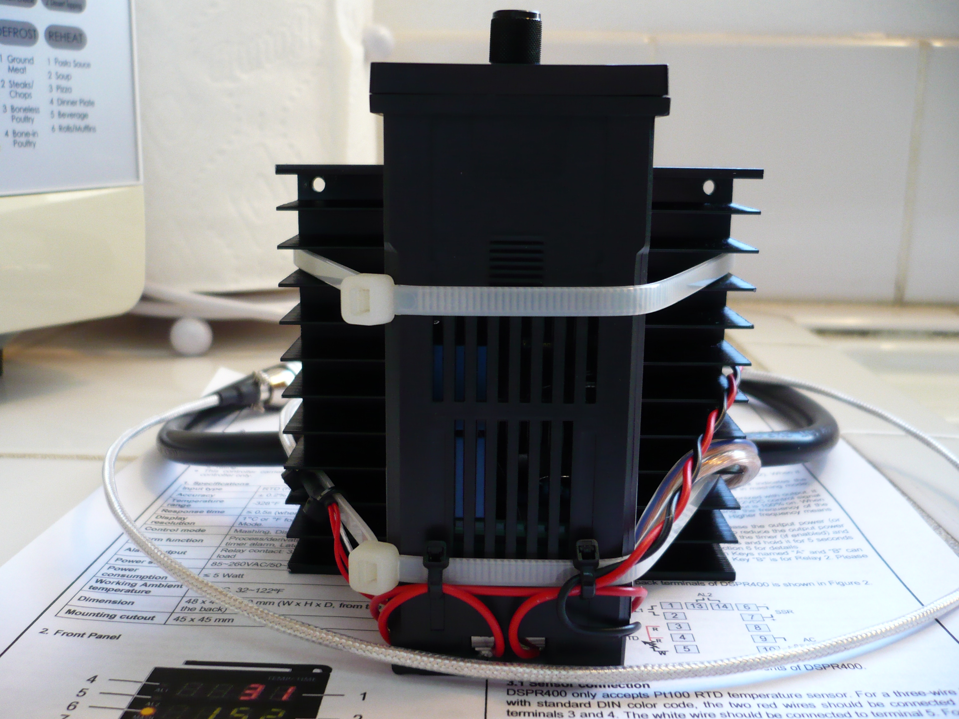
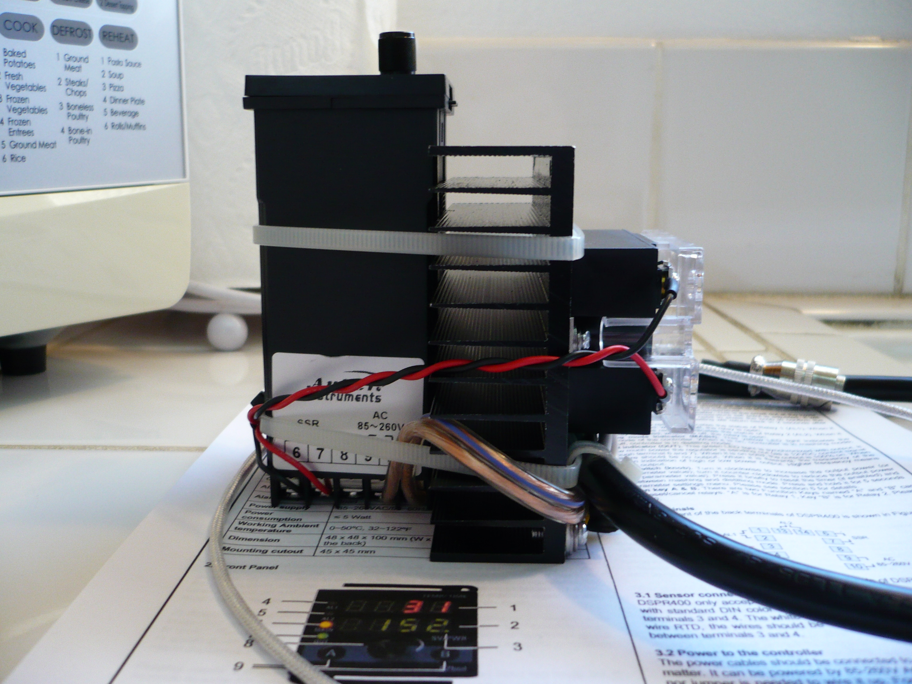
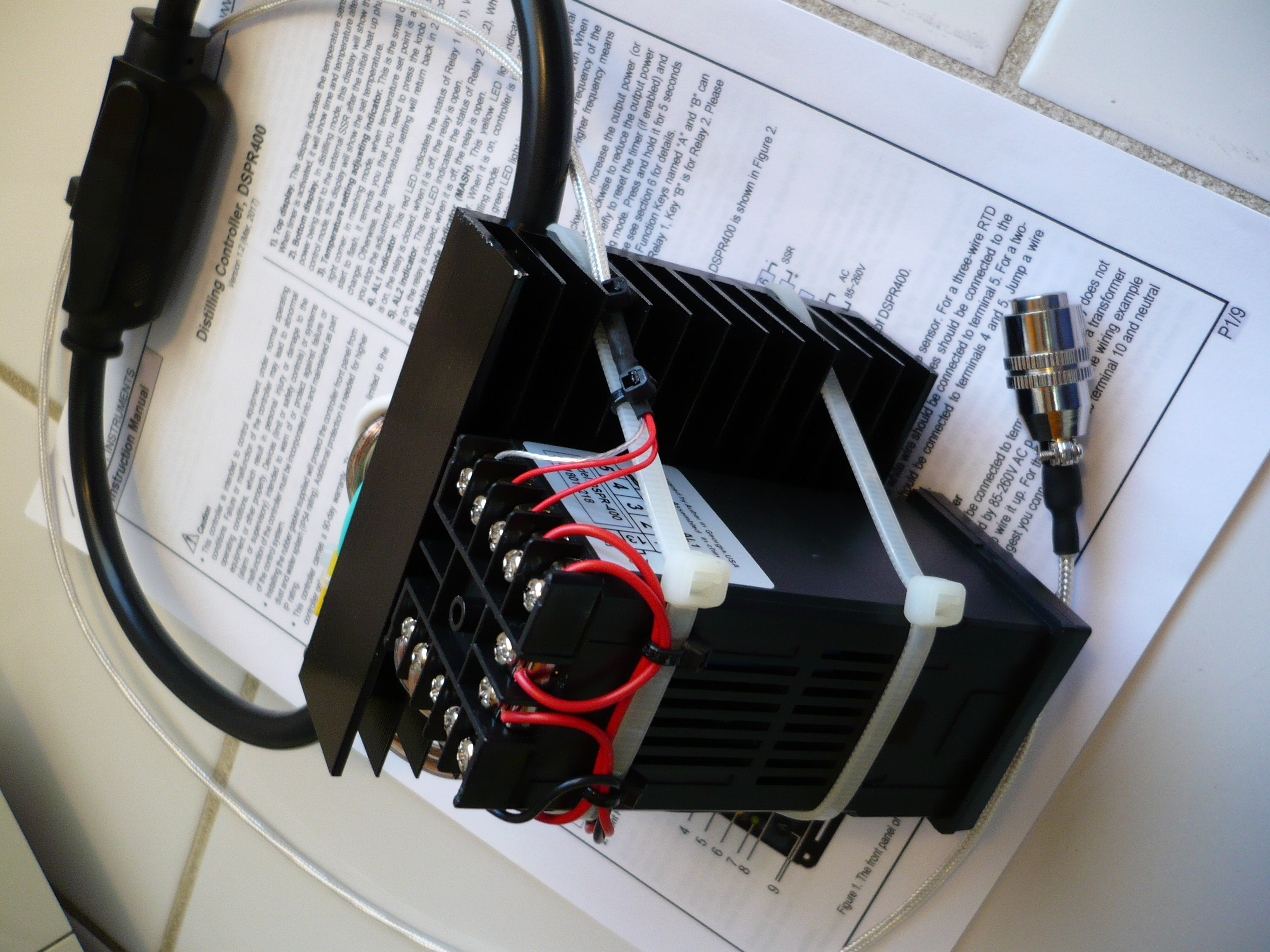
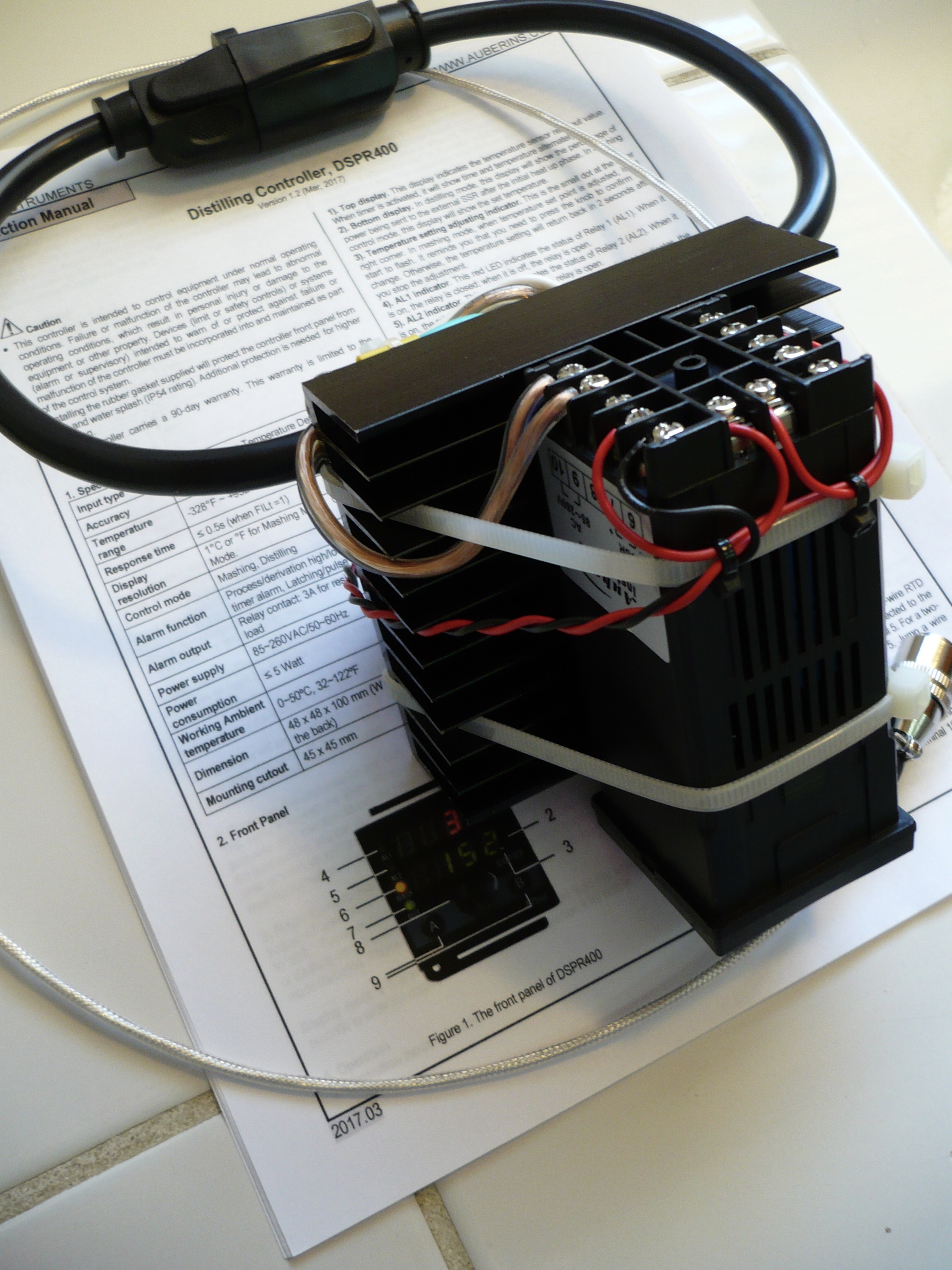
The Auber DSPR400 (DSPR220 with two relays) that I started this thread about is still far superior, I’m rewiring it to support at least one of the internal relays to make it even more versatile, basically I’m adding an ON/OFF function upper set point, which would be on point if I was running a SPD setup… The relays are configurable for almost anything you can imagine possible, and I haven’t even thought about utilizing the timer functions yet. Edit: I assumed the distillation phase end set point could be used to activate the relays, I just read and reread the manual and can’t find that specific option. Imo, this is still the best distillation controller available (outside of an industrial controller that would require Einstein to program and use.)
From the above post: “The Auber DSPR400 (DSPR220 with two relays) that I started this thread about is still far superior, I’m rewiring it to support at least one of the internal relays to make it even more versatile, basically I’m adding an ON/OFF function upper set point, which would be on point if I was running a SPD setup… The relays are configurable for almost anything you can imagine possible, and I haven’t even thought about utilizing the timer functions yet. Edit: I assumed the distillation phase end set point could be used to activate the relays, I just read and reread the manual and can’t find that specific option. Imo, this is still the best distillation controller available (outside of an industrial controller that would require Einstein to program and use.)”
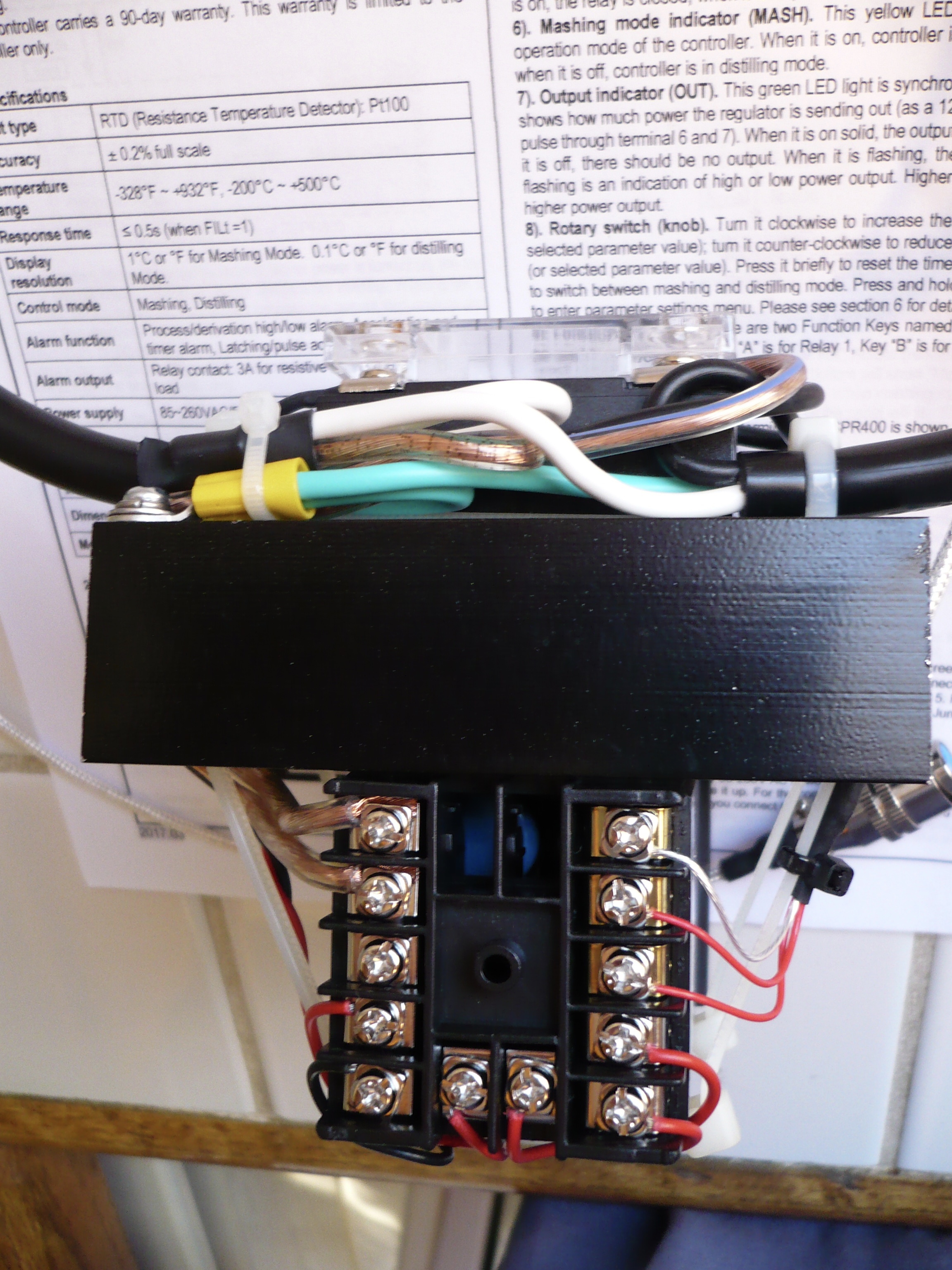
I went through the manual many more times yesterday, and did some experiments this morning with an ohm meter connected to a relay output, and found I I had confused myself, lol. I just finished the rewire and testing, and it works as I had originally hoped providing ON/OFF control at any set point I choose hand in hand with the power regulation function. The trick I came up with to lock a set temp with power regulation on either side of it is still the slickest thing imaginable, but I like options.
I wired the two relays in series with one of the leads to the solid state relay, either one or both can be programed to interrupt the power when and how I want it. Now if I just had a SPD setup to play with (and a new work space, I’m getting the boot the first of the year.) Anyone need a part time lab tech in SoCal, preferably near the coast??)
Sensors: (as the Auber DRSP220 & DRSP400 only accept RTD/PT100 input, and I included in this thread how to wire a rotary encoder power controller in combo with a PID or ON/OFF or Limit controller with a standard K thermocouple input)
First a couple of insightful posts from Beaker,
"I was an electrician on F4 Phantom jets whilst an active Marine. At least for a while. Thermocouples and a whole slew of other sensor types are an electricians responsibility. Oddly the final plug to be hooked to a detachable tactical nuclear weapon for which the Cold War Phantom was designed to carry was not the responsibility of Ordanance but the duty fell to the electricians. A somber moment indeed stepping back from a idling Phantom and giving the thumbs up on that one being ready to go… I will limit the discussion to thermocouples here…
Thermocouple is short for thermocouple pair. It simply means two wires of different metals twisted together at one end and left open at the other end of the pair to connect to a meter. When any two dissimilar metals are in physical contact with each other there is a difference of electrical energy potential between the two metals. As I recall the reason two metals do this was deemed by my Marine Corps instructor to be caused by FM (effing magic) and left it at that when asked.
The charge carried by the metal is directly related to the temperature of it in a linear fashion. When it gets hotter the charge is greater than when it is cooler. The metals will increase their charge they naturally hold (FM) but at different rates from one another as they get hotter. The difference of electrical potential is then measurable by a pretty simple circuit. The terms “voltage” and “difference in electrical potential” are 100% interchangeable.
The type of thermocouple like K just defines what two types of metal wire are twisted together so then a known circuit can be employed. Alumel and chromel were used I believe for a lot stuff like this. My point in explaining all this is that a “thermocouple” is maybe encased in something and maybe has a special plug at the open end but it is simply two dissimilar wires twisted together at the hot end.
When my thermocouples go bad because I bend them around or spill on the junction and such I have no problem at all chopping off the end and stripping and twisting the wires together. Presto. Thermocouple fixed lolz. The twisted wires will corrode at the junction and in fact rust is a direct result of two dissimilar metals in contact with each other but in the form of intergranular metal contamination contact that is unavoidable. Most often chopping off the end of thermocouple pairs and twisting them back will “fix” the pair of wires.
I can tape my thermocouple pair twisted like that to the outside glass at any point in my rig with aluminum heat tape from 3M but normally now just poke the wires between the mantle and the glass.
Do we get paid by the word on this blog?
NOTE: The metal shielding you see on thermocouples can cause hella big headaches and imo are for show only…ducking now… tomatoes fly overhead…
What that shielding actually does in reality is provide multiple opportunities for the worst of the worst of electrical trouble shooting nightmares called simply “ground loops” . I know how to wire to avoid ground loops but as a rule stripping that crap off is precisely what I would do for a fixed permanent install instead of my cobbed up protype lol."
"My PID Control works best to hit target temp when I place the thermocouple sensor between the glass boiling vessel and the heating mantle at the midpoint of the boiling puddle sort of on the side. For me PID sensors in any PID application work best when they are closest to the source of power being controlled (the mantle itself). The algorithms used seem to predict things more accurately that way. For a horizontal run I place a thermocouple on the top of the glass at the neck too during the boil that is hooked to my yellow meter. The mantle controls the heat but the one at the neck tells me when cannabinoid will begin showing up in the first bulb. At ¾ of one micron when that top glass temp at the neck reaches about 132C I can see cannabinoid as a thick resinous material accumulating in the flask neck toward the exit into the bulb. At 140C it runs pretty fast and using time lapse on my iPad it looks awesome lolz. Running hotter makes it immediately darker.
Dialing this in is pretty easy when the probe is just outside the glass and between the mantle. I have tried other places but my PID Control has an overtemp feature to prevent mantle damage so the sensor must be in contact with the mantle for this to work."
I agree with everything Beaker’s saying, but there are many K thermocouple choices not found at eBay that might be slicker if you have the money and time for experimentation, here is but one from Omega,
“OMEGA offers a line of butt- welded bare wire thermocouples that provide a faster response time and can be used in tighter spaces than standard beaded wire thermocouples.”
A pot of coffee and a search of K thermocouples at Omega will overwhelm you.
Same goes for RTD/PT100 sensors, eBay has nothing compared to Omega. Of the many choices, what caught my interest is the thin film elements (it’s just the element and a couple short bare leads, you need to make up the rest of the sensor assembly yourself,) only $50 for five.
Testimony power regulation is superior to temperature regulation, and a summary of what has been presented in this thread:
gonzo
“I find a variac gives me the best temperature control and the most even heating, far above a PID which is above a dimmer. A guy from california is selling a good variac for 38$ shipped, I got his 46$ version (10amp).”
Five ways to precisely regulate power:
1 Variac alone (a 20 amp unit from eBay for about $75 is recommended)
2 Rotary encoder power regulator with solid state relay (Auber DSPR1)
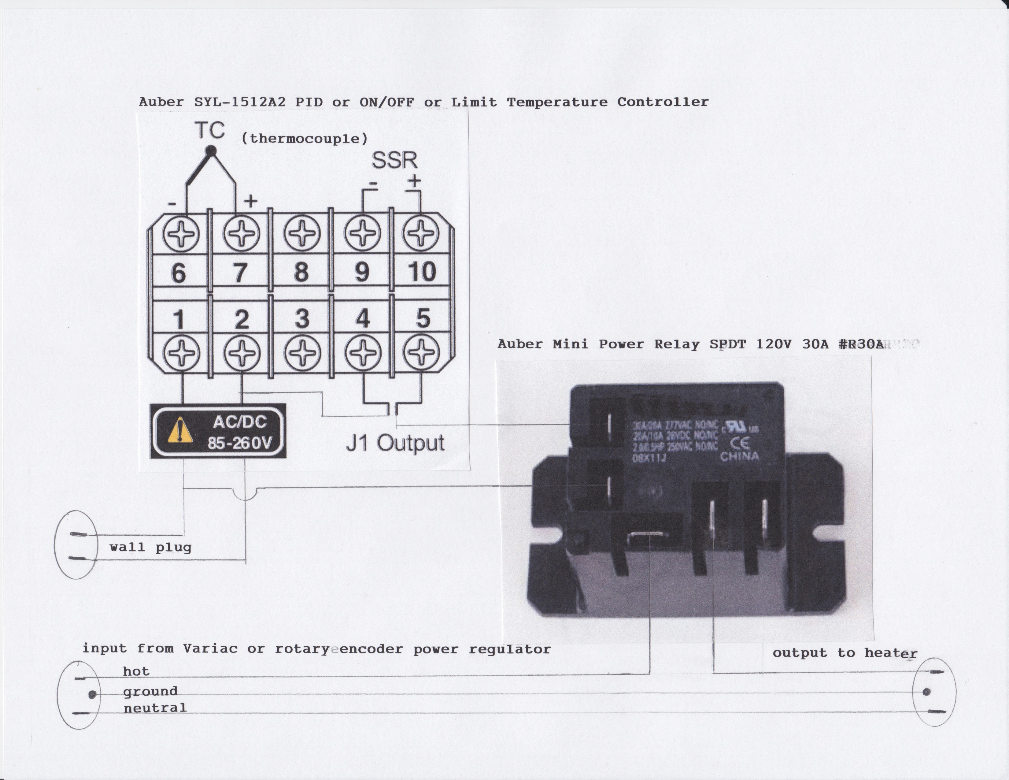
3 Temperature controller with PID or ON/OFF or Limit function with an external heavy duty mechanical relay* to control the temperature when using either a Variac or rotary encoder power regulator (Auber SYL-1512A2 temperature controller)
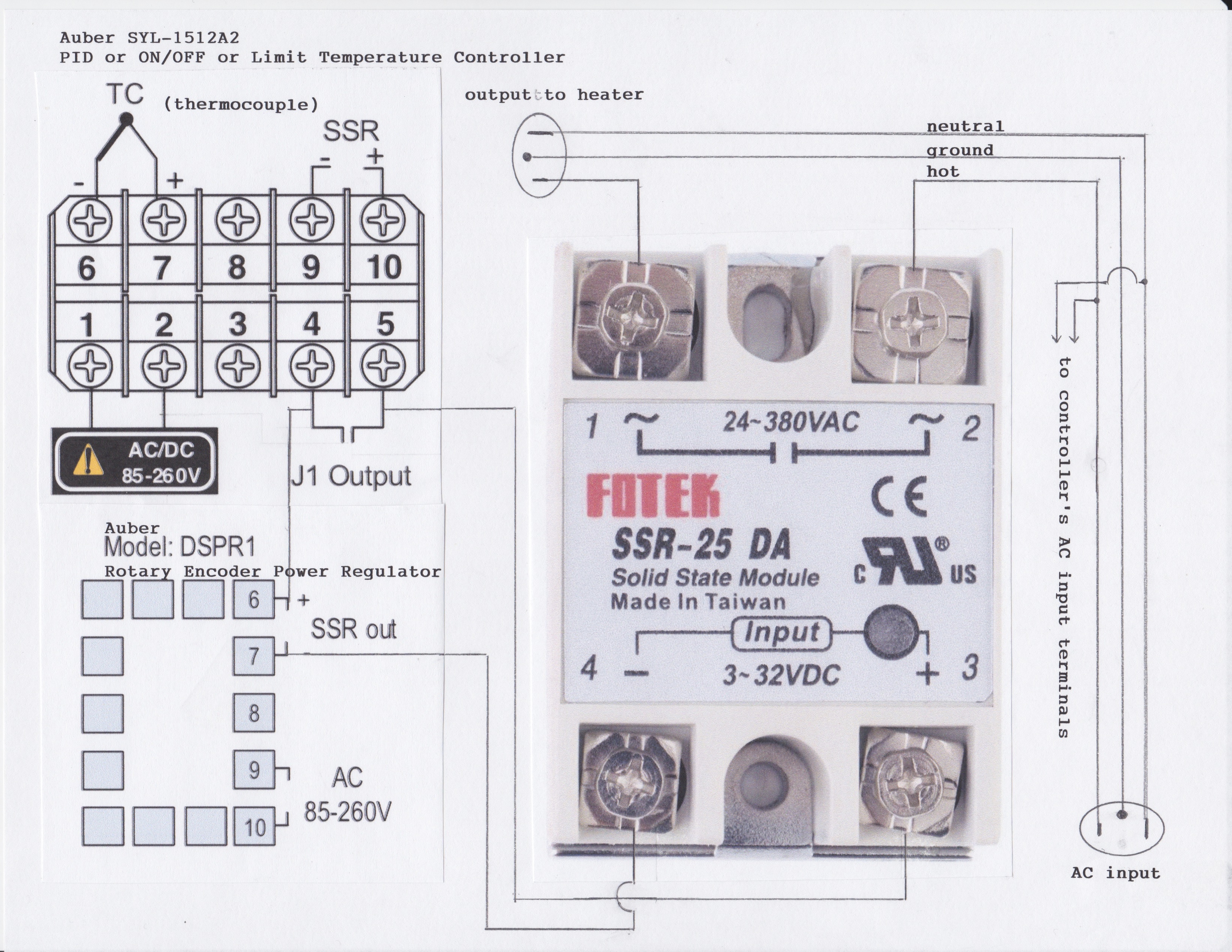
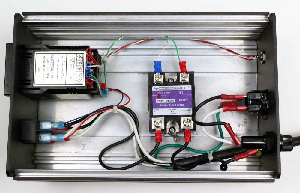
4 Temperature controller with PID or ON/OFF or Limit function with it’s internal mechanical relay* used to interrupt the solid state relay signal from a rotary encoder power regulator (Auber SYL-1512A2 temperature controller and a Auber DSPR1 power regulator and a solid state relay)
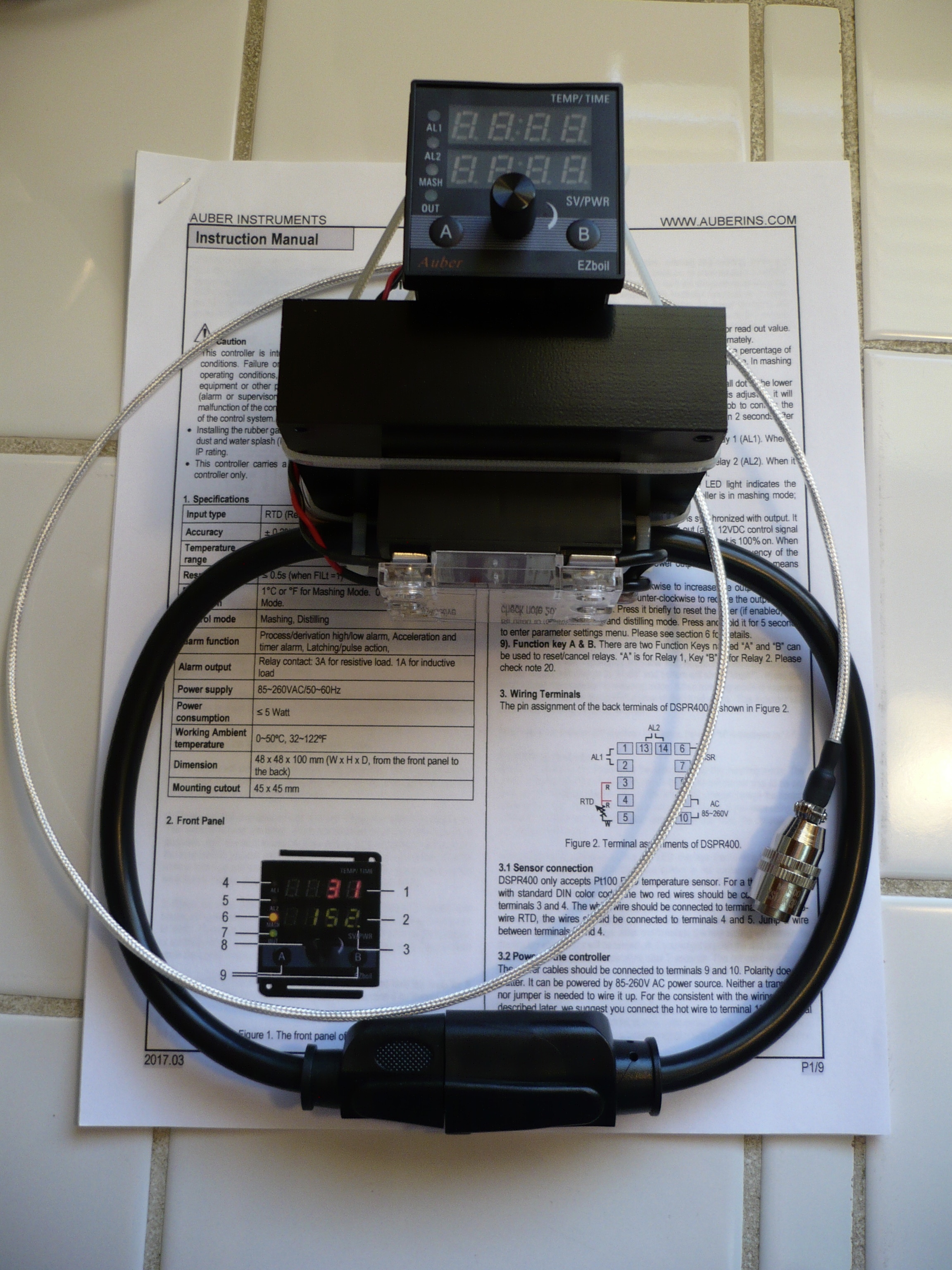
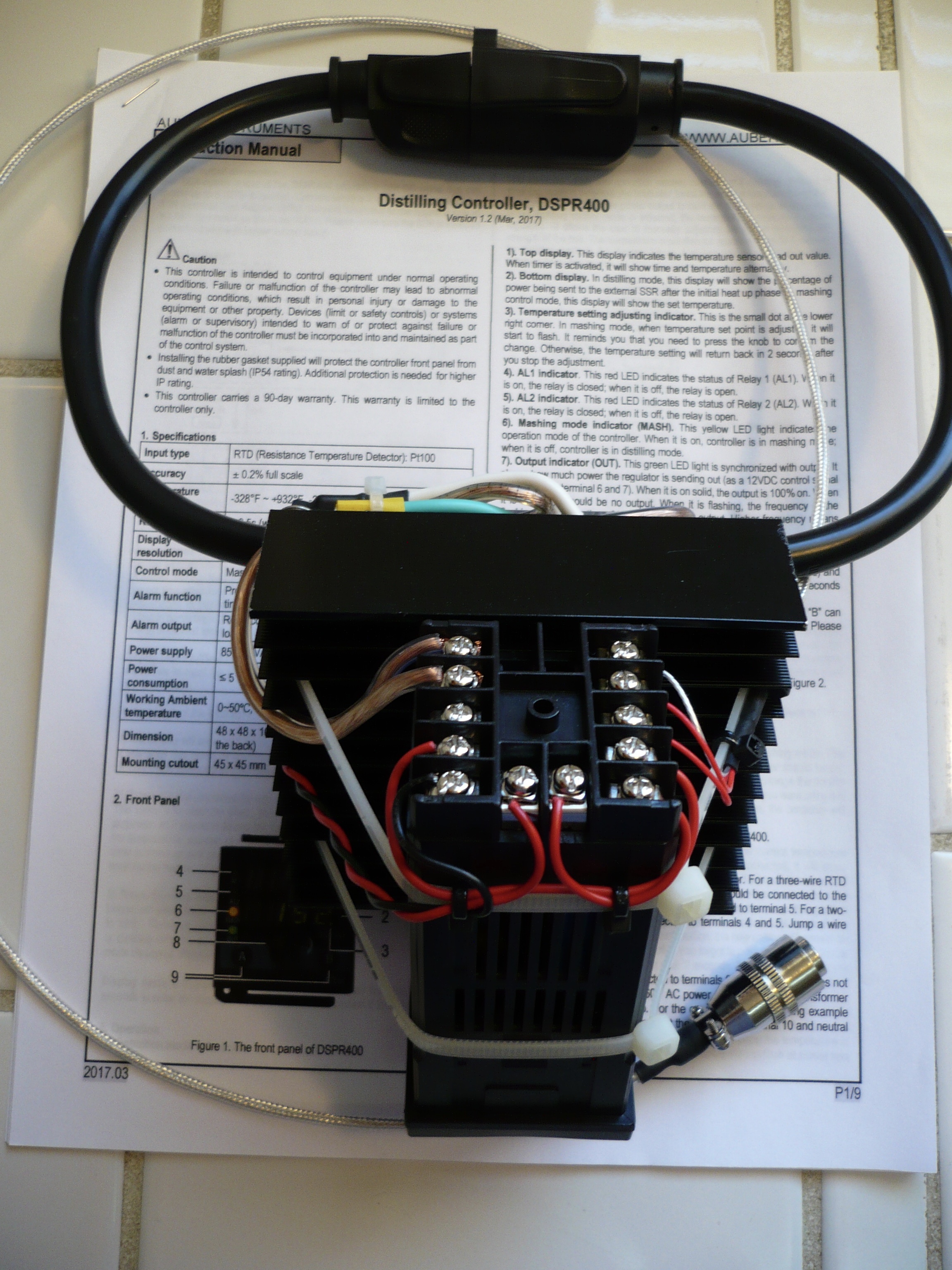
5 Rotary encoder power regulator designed for distillation with solid state relay (Auber DSPR220 or DSPR400)
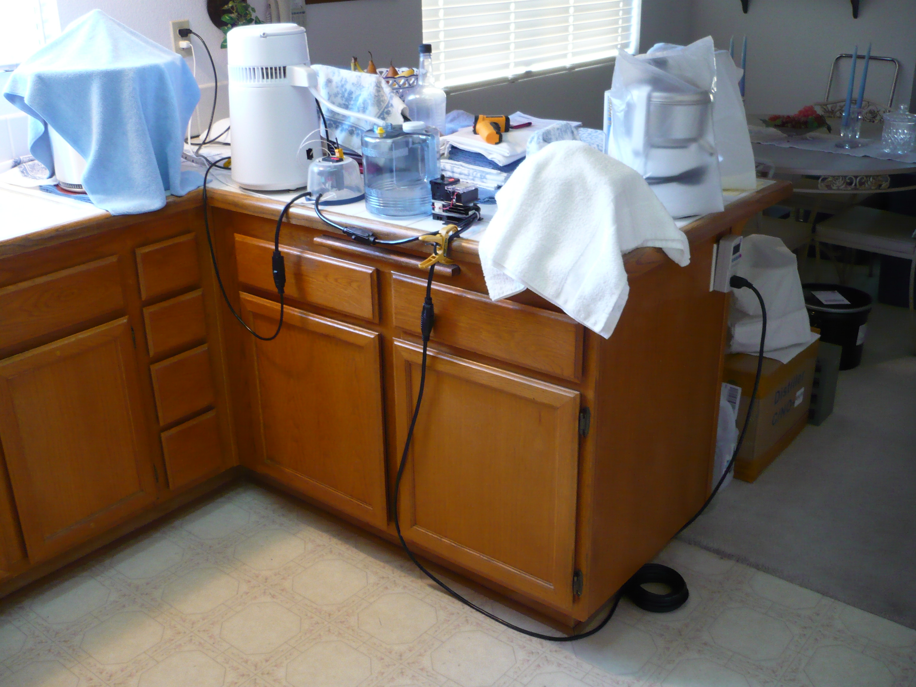
How I assembled and set up of a temperature controller with mechanical relay,
From the final link (setting the controller cycle time for the mechanical relay)
“I don’t think I posted the info for the SPST relay I’m using. It’s the same brand and rating as the little mini power relay Auberins carries without the superfluous normally closed contact.
The initial controller setup is straightforward and simple, and changing between PID, on/off, or limit, and adjusting set point is just as hassle free. One note (this from the controller manual,)
“Note 10. Cycle rate (ot): It is the time period (in seconds) that the controller uses to calculate its output. e. g. If ot=2, and the controller output is set to 10%, the heater will be on 0.2 second and off 1.8 seconds for every 2 seconds. Smaller ot value results in more precision control. For SSR output, ot is normally set at 2. For relay or contactor output, it should be set longer to prevent contacts from wearing out too soon. It normally set to 20~30 seconds.”
Instead of upping the cycling rate to 20-30 seconds to accommodate the mechanical relay, I went with the lowest suggested value I could find, 8 seconds, though I just found another reference stating 5 seconds. I’m not worried about wearing out the relay contacts, I just want to avoid pulsing them, so I may experiment with lower values to find out just what’s actually optimum for this situation.
Five seconds works fine, any lower and the clicking gets annoying.”
That’s all I know, sorry for the rambling presentation, but it should all be there if you go back and dig through the links.
3 Temperature controller with PID or ON/OFF or Limit function with an external heavy duty mechanical relay* to control the temperature when using either a Variac or rotary encoder power regulator (Auber SYL-1512A2 temperature controller)
I recommend the Auber external relay, they include the terminals - nice. The terminals can be crimped with a pair of needle nose pliers if you don’t have the correct tool.
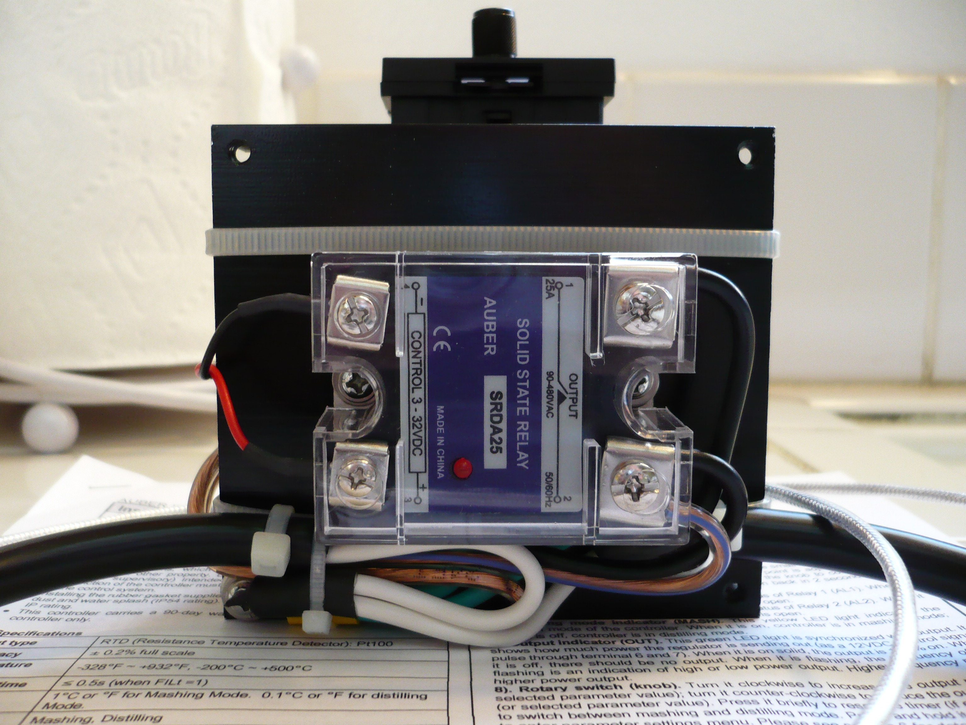
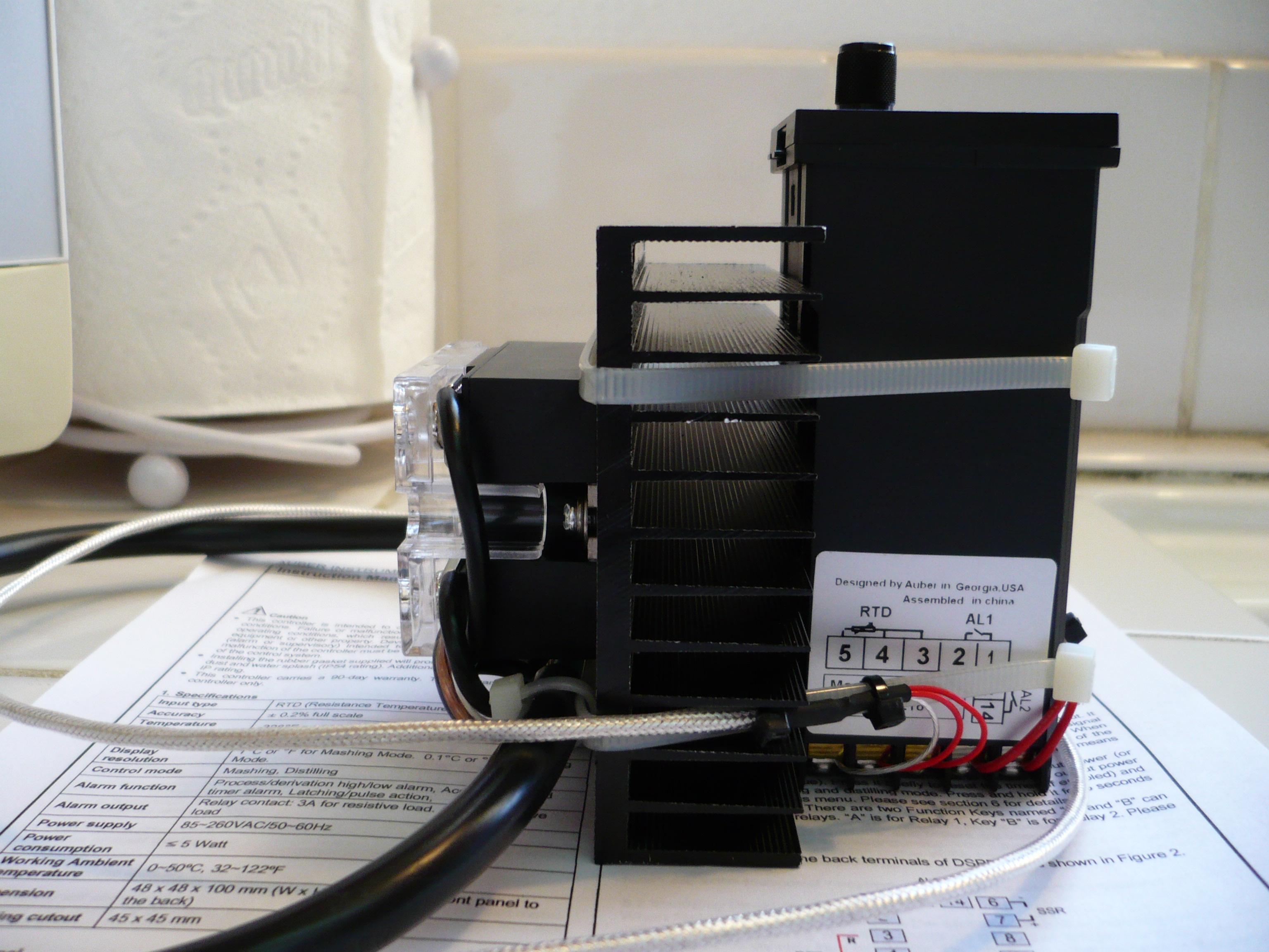
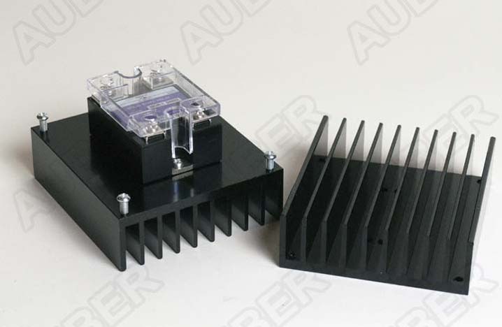
The rotary encoder power controller requires a solid state relay, 25A should do for most situations, it needs to be mounted to a heat sink. I recommend the Auber heat sinks, they include the thermal compound and screws - nice.
4 Temperature controller with PID or ON/OFF or Limit function with it’s internal mechanical relay* used to interrupt the solid state relay signal from a rotary encoder power regulator (Auber SYL-1512A2 temperature controller and a Auber DSPR1 power regulator and a solid state relay)
Both controllers need AC power input, the actual connections have been left off the diagram.
Assemble and wire the pieces in a Tupperware container or actual electronic project box and you have a better temperature controller with power regulation than the $1,300 device from Lab Society, or any of those from J-KEM or Glas-Col. That said, the Auber DSPR220 or DSPR400 Distillation Controllers are even better tools considering all the programing options they offer.
Why you need a controller and what kind. (Electric heat)
Postby Prairiepiss » Wed Nov 06, 2013 10:00 am
There is always a lot of confusion about the need for a controller when an electric element is used to heat a still boiler and or an electric heat source like a hot plate. So I would like to clear things up a bit with this post. It’s not about which controller is best to use. There are plenty of threads about the different types of controllers. This thread is about why you need one. And what that controller needs to do for you.
Since you are reading this I am assuming you have already researched and learned the basic theory of distilling, if you have not, you should do so before getting too deep into this subject, otherwise you won’t fully understand what is being said here.
Basic distilling:
You need to boil the liquid in the still boiler to produce alcohol vapors that can be recondensed into a higher ABV distilled spirit. The temperature that that liquid will boil at is dictated by the ABV of that liquid since it is a mixture of alcohol and water. It will be somewhere between 173f/78c (boiling point of 100% alcohol) and 212f/100c (boiling point of water). The higher the ABV the lower or closer to 173f/78c the boil point will be. The lower the ABV the closer to 212f/100c the boiling point will be. There are charts available to figure exactly what that boiling point will be.
Alcohol content of Wash
Just remember. You cannot control the temp of the boil the amount of alcohol does this.
This now leads me to why you need a controller for your electric heated still.
You need to be able to adjust how fast the liquid is boiled off. This controls how much vapor is produced. Less heat makes for a slower boil. And will make lower amounts of vapors produced. More heat will make the liquid boil faster. Producing more vapors. You need to be able to adjust the amount of heat. That you put into the still boiler. So you can adjust the amount of vapors produced and sent into the still head. I will give you a couple of examples.
Pot Still
On a pot still you control the takeoff rate not temps. To do this you need to control the amount of vapors that are sent to the condenser. Again The slower the boil less vapors are made. So you get a slow takeoff speed on a properly configured system. A steady takeoff rate of drips per second should be achievable. In the lower heat settings when you crank the heat up the amount of vapors created by the faster boil increases, thus more vapors are sent to the condenser and the takeoff rate increases. Do not exceed the condenser limitations. Allowing alcohol vapors to be pumped into the air. The top speed you can take product off is limited by the product condenser being used in your still. But a good takeoff speed for a pot still is somewhere between a steady broken stream and a steady twisted stream. You can only achieve that by adjusting the amount of heat put into the boiler to get the liquid to boil off at the correct rate to produce the right amount of vapors. If you don’t have control over the heat it will either be to slow of a takeoff speed or to fast of a takeoff speed. Vary seldom can you achieve the correct takeoff speed without a controller. Keep in mind that the ABV of the liquid in the boiler will affect the amount of heat needed. So a 10% wash will take more heat to get the correct takeoff speed than a 40% low wines still charge. So you need to be able to compensate for this by being able to adjust the amount of heat. A setting that works for a 10% wash will be too much for a 40% low wines so the takeoff speed would be too fast. As the run progresses the ABV in the boiler goes down thus the heat needed to maintain the same takeoff speed will increase.
Reflux Stills
There are many different types of reflux stills but the same basic rules apply to all of them.
On a reflux still you want the proper amount of vapor sent to the column to produce the proper amount of reflux for the still to work at an optimum level. Too little heat results in too little vapors and reflux giving you poor results and shows up as higher temps on the columns thermometer. This results in a lower ABV product because not enough reflux is returning to the column for the packing to work properly. Not having the proper amount of reflux returning to the column will not allow the needed column temp gradient to be achieved, more hot vapors than cooler returning reflux showing a higher temp than wanted. Now a too high of a heat input creating to many vapors will more than likely flood the column where there is too much reflux returning to the column and to much vapors coming from the boiler causing the vapors to hold the reflux in the column not allowing it to return to the boiler. This will cause a safety problem and poor performance. You need to be able to adjust the heat input to achieve the correct amount of vapors to achieve the correct amount of returning reflux and rising vapors in the column. This is different for every still. And as above the ABV of the boiler charge will also change this so it needs to be adjusted for your particular still setup. There isn’t a one size fits all type heat setting it’s all as per still.
Now on to the kind of controller like I said this is not about the best controller. It’s about what that controller needs to be able to do for you. The controller needs to be able to adjust the amount of heat being put into the boiler. In a steady variable amount you want the heat to be as steady as possible. You do not want it cycling on and off wildly. If cycle times are more than say one time a second. It’s more than likely not a good choice because every time it cycles on more vapors are created. Then when it cycles off no vapors are created and you get surging. It would be like if you were trying to use a hose and your kid was around the corner pinching off the hose and laughing at you because the hose sprays then shuts off, then sprays and shuts off again. This variance in vapor amounts can and will wreak havoc on the still operation causing surging which in turn will cause smearing of the heads hearts and tails and it can give you false readings on a thermometer in a reflux column.
The other thing you do not want is a controller that works off of temps. A thermostat controller or PID controller (without manual mode) are examples. First off we can’t control a still by boiler temp. As it will be ever changing and these types of controllers cycle very widely. They reach the set temp while at full power then shut off all power till the temp drops below the lower setting which is usually a long time span. Since it’s trying to control temps and you are trying to control amounts of vapor produced the temp settings usually get set high so you get really long surges of full power heat. All this creates bad surging within the still and the same holds true as stated above about the surging.
There are many types of good controllers out there. And many good threads on all those types of controllers. Please do your own research as to which one of those will be best for your situation. As long as it does what I mentioned above it will serve you well.
You need to catch the drift for yourself, but real chemists in real labs still use and prefer a variable power regulator to a temperature limiting PID controller for distillation.
Don’t be suckered by the Chinese import mantles with PID controllers!!
Here’s an up to date lab site, and they’re still promoting power regulation… not a single word you should invest a few dollars more on a PID controller,
Here’s their controller page, and most of the controllers listed are power regulators, not PID controllers!!
I’m deffinately going to be racking your brain when I mod my 1l and 500ml mantles with those thermocouple i scored on Amazon that soxhlet posted the other day
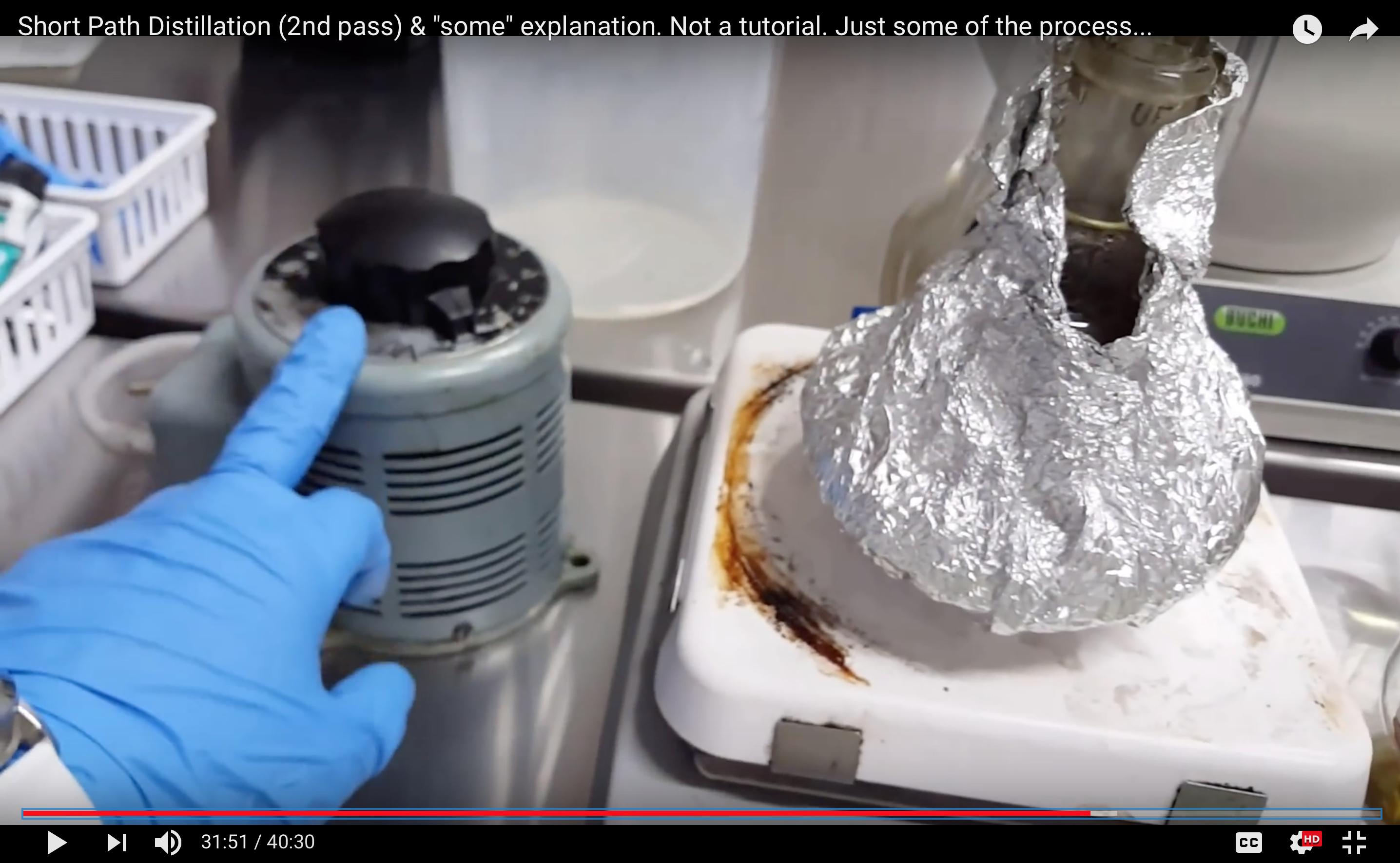
I found a fairly recent video of a guy running a SPD with a Variac, and it’s smooth… he states later in the video that he is indeed using the Variac. I queued it up to near where the distillation starts: https://youtu.be/J7ux2EoWzgI?t=543
I decided to put together a controller using the DSPR220. I’ve used both a variac and PID to control my 2l setup before. Although, I like the variac I did have a hard time really dialing in a set temperature with it. The PID worked pretty well, but some of the features on the DSPR220 seem like they would come in handy. I’ll have to see how she preforms.
Beautiful looking, puts those tin cans J-KEM, Glas-Col, and Lab Society offer to shame!!
One caveat though before others jump in to emulate you, spend the extra $12 for the DSPR400, same controller, but with two programable relays.
Auber DSPR220/DSPR400 page:
You may not think you need, or would have any desire the relays, but you can easily insert them at any time in the signal path to the solid state relay by moving a wire and adding a jumper or two as I have, and then have an upper ON/OFF temperature set point or additional timer control. Or, the relays can be used to control a low wattage pump to your condenser, or used to drive a high power relay or contractor to control your chiller, etc.
I sincerely hope you’ll take the time to post up a full review of your experiences with the DSPR220 JacobsLadder, and if you’d like to help those without your skills, maybe you could share a little how you assembled your controller.
Geez your just making all types of cool useful electronics arent ya. When are you posting your vac gauge project stuff and selling the premade stuff. You really have a knack for this stuff. Maybe you should try to sell some of these too. I bet you could have a pretty solid business with just a few DIY Tools and Kits.
It wouldn’t take anytime to swap out the 220 for the 400. I just didn’t see many need for the extra relays. The box isn’t exactly big on the inside either. You might be able to fit another ssr or 2 inside, but most likely would need them externally mounted. I’ll give an update on its performance as soon as i can. I’m putting together a 5l shortpath at the moment and will be able to test on both.
The vacuum gauge stuff is in the works. I’m working on the initial dual sensor for sale prototype currently and taking care of some production issues that have come up. Just trying to make it more lab friendly and easier to put together.
The diy version is moving foreword as well. I’m putting together the eagle files, schematics, and a write up. I unfortunately have a substantial business to run on the side. So, the hobby stuff has to take a back seat sometimes. It’ll probably be ready in a week or so if things don’t get crazy.
If you like the recent stuff you’ll probably like my next adventure. I’ve sourced the parts to put together a spectrum analyzer for short path terp/heads/main/tails identification. I’ve seen breakingdabs using one on Instagram recently and thought it looked like an achievable device. It might even be an easy enough project for a diy kind of thing. That’ll have to be determined later though.
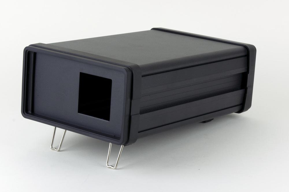
Auber has some instructions for cutting openings, my father taught me the masking tape trick back in the early '60’s, he was a sheet metal fabricator until he damaged his wrist. I grew up with tools and projects. Link to the instructions,
$53.67 for that box!! When plastic became readily available my father chose it over metal when possible, so may I suggest a large inverted Tupperware container for the project box? If you use Auber’s external mount heat sink, you simply cut a hole in the container the size of the solid state relay and fasten it with the supplied screws. That’s the heat sink I used for my assembly, it’s so oversized you’ll never have to worry about it getting hot.
A power switch and fuse are really unnecessary, but you’ll probably want a sensor connector, unfortunately all the RTD/PT100 connectors have solder terminations, so maybe just bringing the sensor cable through a hole in the box, and connecting it directly to the controller would make the project simple for even those without advanced skills.
If somehow I find a new home to live in, I’d be glad to assemble these anyway anyone wants with whatever parts for a small fee. I’m not about to offer assembled units kept in stock, as soon as I do, Best Value Vacs etc. will copy it, and offer it for cheap. Been down that route with other projects.
Hope that helps, thanks again JacobsLadder for giving it a go!!