Description: Material skid, surge tank skid, crc skid, ffe, (2) 220 lb solvent capacity tanks, manifolds and ball valves, detailed description below
Price/MSRP: $250,000
Current location of item:Portland Oregon
Estimated lead time: Ready now
Fulfillment: local pick up
We all know processing takes time and experienced extractors know that using your time wisely means utilizing as many processes as you can at the same time.
For example; a simple bho operation has many processes. You have to prepare biomass, load biomass, extract biomass, remediate biomass, recover solvent, collect the end product, cook product to the right consistency (make shatter, sugar, or diamonds) and then purge the residual solvent out of the end product to send to packaging.
Clearly there are several steps involved and the experienced processor knows you can’t do one of those processes at a time and have a productive day. You need to have biomass being prepared while other biomass is being extracted, filtered and recovered of solvent while you have batches cooking to consistency and other batches purging residual solvent to have constant production flow with product coming out regularly to make the most of your time.
We also took note of the troublesome process of processing massive amounts of crude (skipping crc) and then redissolving the crude extract later to be filtered. We wanted to design something that could move through lots of material really fast without having to redissolve in solvent.
With that in mind we designed this hydrocarbon extractor with ideas coming from half a dozen other extractors who are actually in the lab producing everyday, not a group of engineers who know how these should work “in theory” and our engineers showed us how to make our vision become a reality.
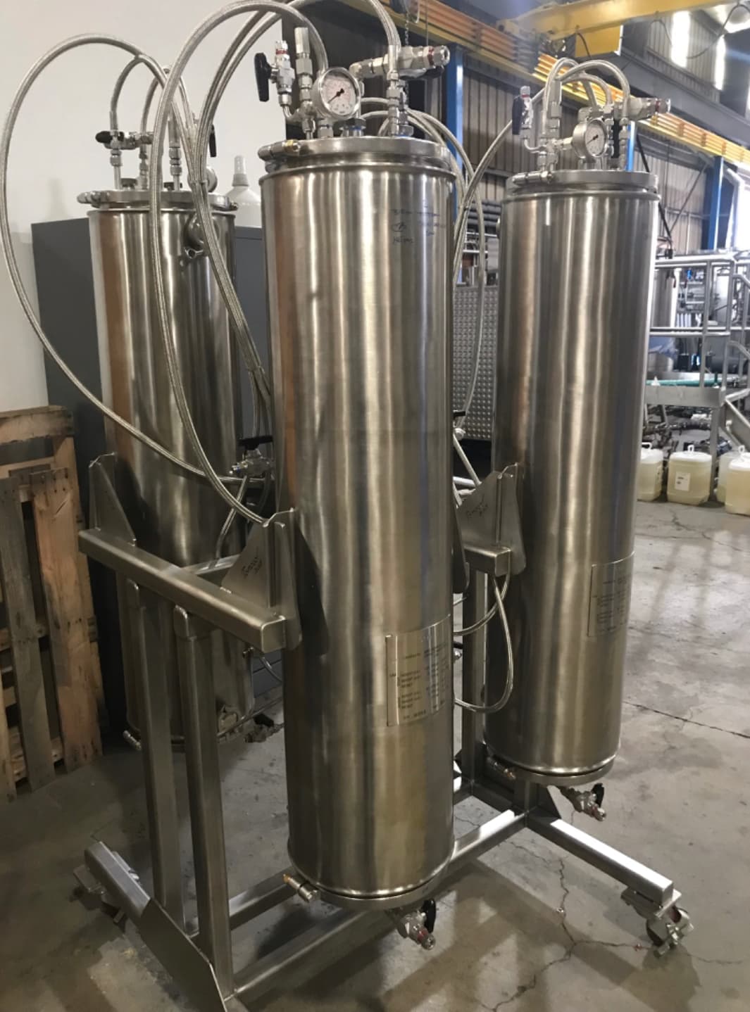
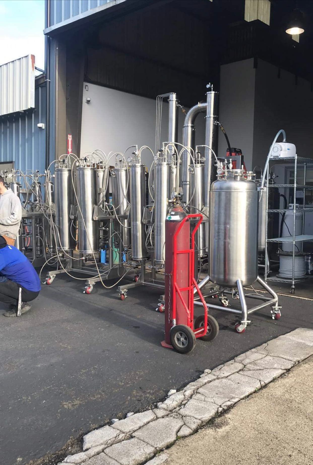
The entire system consists of three separate skids, two 220 lb solvent capacity (with 80% headspace) and a falling film evaporator.
The first skid is the material column skid equipped with (4) 6x48 inch jacketed columns. The jacketed columns allow for chilling and heating fluid to dispensed to the material allowing you to cool the columns to the desired extraction temperature and shortly after your material columns are cleared of solvent, heat up to recover residual solvent in biomass.
Skid number two is (4) 10x48 inch jacketed “surge” tanks. These tanks are designed to hold 80 lbs of solvent (at 80%). This allows you to extract with 8 lbs per lb of solvent if you can fit 10 lbs of biomass in the material column. The bottom drain on the jacketed material columns lead directly to the top of these tanks and feed into them.
The third skid is (4) 4x48 inch crc columns with sintered disc plates and sight glasses in each. The columns are massive, designed to hold enough media to go through 100-200 lbs of biomass without needing to change media. The amount of biomass you can extract before changing media is subject to how much oil is on the biomass and the quality of the oil extracted.
The falling film evaporator is 8 inches wide and 7 ft long. This allows for massive evaporative and condensing surface area. Having this much evaporate and condensing surface area allows you to recover up to 20 lbs of hydrocarbon solvent per minute making recovery times as fast as your injection speed.
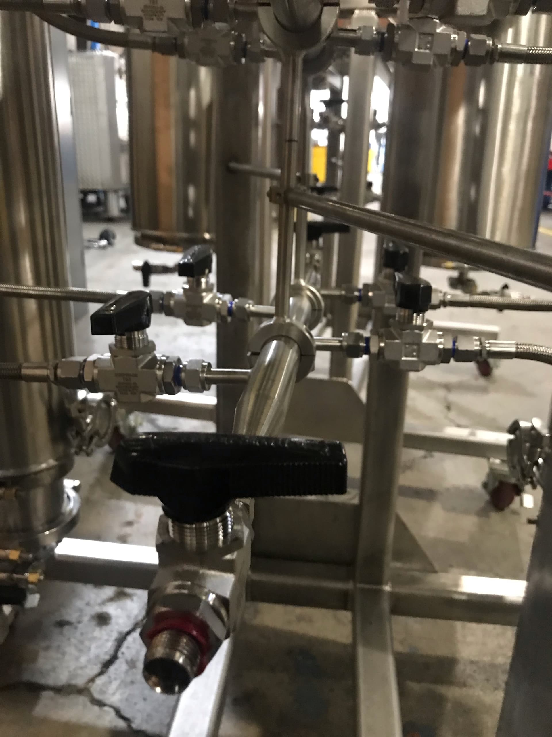
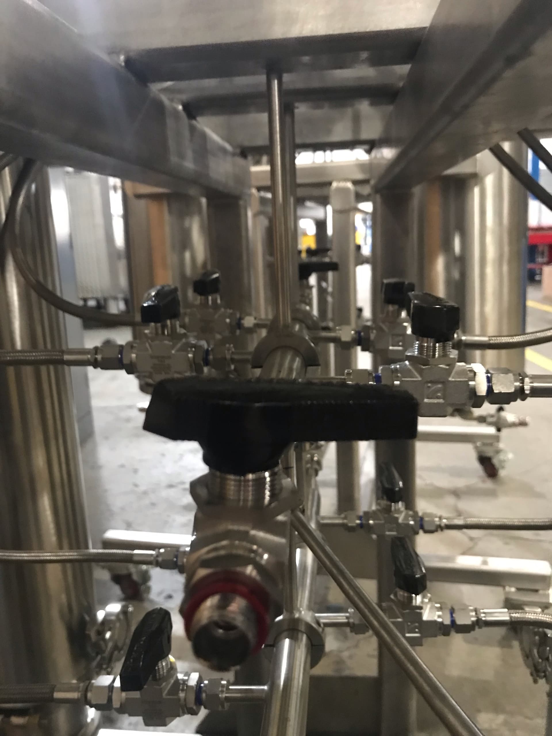
What really makes this machine stand out from others is the manifold system. The manifold system is a three part ball valve and hose combination (can be hard pipe compression if modified). There is a manifold for each; liquid solvent, nitrogen and vacuum. Each portion of the manifold connects to every single vessel on the entire system and is easy to operate by ball valve. You can pull vacuum, push nitrogen or flood solvent to any vessel. This is especially important for a few scenarios. All three skids and the falling film evaporator are connected through the manifold.
The first scenario where this manifold comes in handy is using powdered media blends. Powdered media blends work best when they are pre soaked with solvent to avoid channeling. This manifold makes flooding solvent into the crc column a breeze. You also can use it to rinse media that’s done being used before switching out for new media without having to stop extraction.
The second important situation this manifold takes the cake is during normal operation. This system is designed to operate as many processes as humanly possible. This plays out by being able to pull vacuum on your material columns, flood the columns with solvent, using nitrogen to build pressure and push the solvent into the surge tank and letting extra solvent run over the material. Once solvent has been pushed through to the surge tank, you will begin pushing nitrogen into the surge tank to feed the crc columns. The sight glass and ball valve at the bottom of the crc column allows you to control flow to get the colored desired if granules are being used for filtration media. At this point you will either begin heating the jacketed material columns to recover the residual solvent or vapor push through the material column into the surge tank. There is a ball valve manifold that leads solvent evaporating off the material column directly to the condensing side of the ffe so you can recover the solvent coming off your crc columns at the same time as you’re recovering your material columns.
Once your material columns are finished recovering, you can bleed off any residual pressure and start taking the material column lid off, remove material socks, cool the column and begin vacuuming down the system. If the first batch isn’t finishing being removed from the surge tank you can add this batch over the top of the previous so your time between runs is drastically minimized.
Also worth noting, the falling film evaporator has (4) 1/2 inch connection ports which lead from each individual crc column. You’re able to recover as much solvent coming out of the crc column as is allowed. You’ll notice I mentioned that the falling film evaporator is capable of recovering 20 lbs of butane per minute. When granular filter media is used, we see the color come out best at around 3 lbs of solvent injected per minute. Given there are 4 crc columns, you would regularly see about 12 lbs of solvent recovered as that’s what’s allowed to run through the crc column. Less if powdered media is used.
The system also incorporates (2) 220 lb solvent capacity at 80% ASME certified solvent tanks. We found that using two tanks allows recovery and injection to take place at the same time and works far better. Having a second tank to just recover into also gives the liquid recovered a direction to feed too.
The rack the falling film currently sits on places the falling film at 11 1/2 ft tall. This is because there are (2) 100 lb solvent capacity tanks on the bottom of the falling film. The heat side of the falling film has plenty of room for whatever oil is created. The cold side of the falling film has enough room in the tank to valve off during recovery so you can move liquid butane from your recovery tank to your solvent injection tank without stopping recovery to streamline the process and never have to shut down operations throughout the day. The falling film can be disassembled and placed on a different rack without the two tanks on the bottom and be below the 10 ft ceiling height that is common with most extraction booths
With the vessel sizes of this machine, it is designed to only run butane, not propane butane blends. We felt that with recovery times being as fast as they are on the falling film evaporator, there’s no need to use a solvent with a low boiling point like propane as this only complicates and adds to chiller costs. We also decided that color wasn’t a factor anymore because we have media filtration capabilities allowing us to control the color coming out every run.
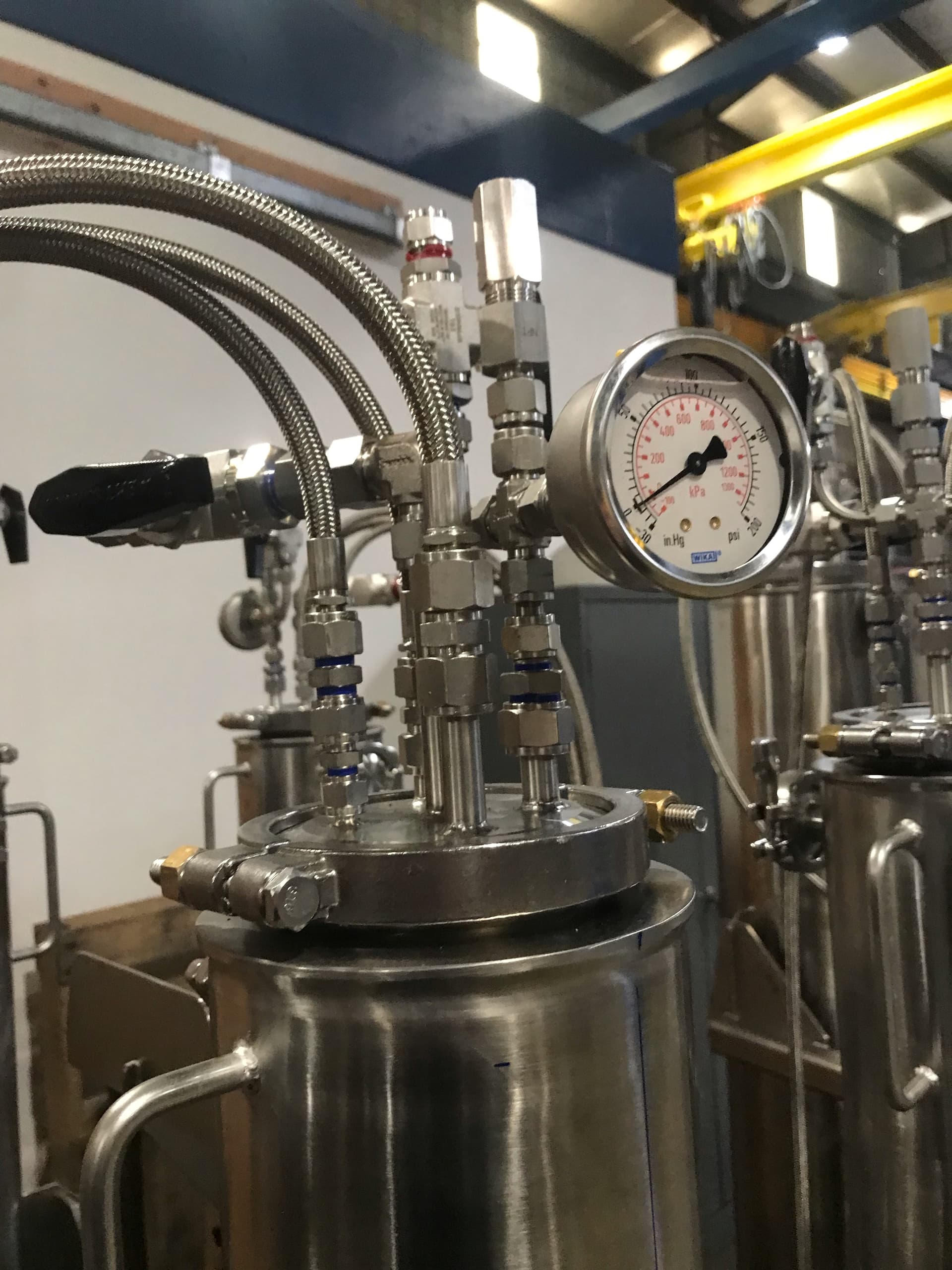
This unit is ASME certified and built in Oregon as well as peer reviewed by a third party engineering firm. Every single vessel has pressure relief valves set to below the burst pressure of the entire system and every single vessel is asme stamped. Every fitting on the system is compression. Solvent line and vacuum lines are 1/2 inch, nitrogen lines are 3/8.
We know this machine is capable of running through at least two runs per hour realistically including setting up and taking down when the machines ancillary equipment is ready to run. Each run consisting of running material in all four material columns. Run times can be dramatically reduced if no filter media is used and the desired end product is unfiltered oil.