I appreciate the vote of confidence lol.
I’ll try to not nerd out too hard about functional safety but it’s one of my favorite subjects.
Strictly speaking, HMIs should never be used as safety devices because they not only rely on non-safety hardware but they usually run on some sort of windows OS and we’ll, yeah I need not say any more.
The issue with the e-stop button is usually this: there are 3 types of e stop.
Type 0 is just a power cut that latches. It is like 95% of e stop devices.
Type 1 is a controlled stop. This is what we want here. It’s common for things like saws or other things that spin fast and need to be slowed before power can be shut off.
Type 2 is a powered e stop. This is what we run for our CO2 extractor and should really be used on any large cryogenic system. These are used for things like nuclear reactors where you need to maintain instrumentation to keep making safety decisions and allows the system to triage. They’re very expensive lol.
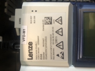
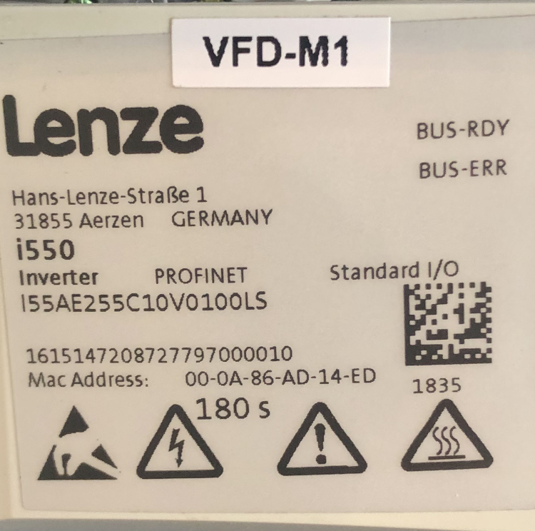
I would imagine the e stop on your CUP is a type 0. What that means is the drive is just going to lose power, which is kind of the right thing because unless you buy a mega expensive drive, it can’t be depended on for critical safety functions. But, without the clever design that we’re going to come up with here, if you just cut power you lose active braking.
It’s pretty cut and dry if you do a risk assessment that the risk of getting electrocuted from relying on the e-stop fallaciously to isolate power inside a sealed panel is WAY less than throwing your fuge across the shop because your wooks decided to dry their boots in it (hopefully not but I like colorful examples).
The good news is converting to type 1 from type 0 (while it will probably void your warranty) is fairly simple in this case. There are two options and I really like the PLC option but it’s maybe overkill here depending on how much work you want to do.
The non PLC option is this:
*Change the wiring through a safety rated delay-after-break relay timer and set the time for the programmed braking time on the drive so that the relay stays powered but the signal is broken when you punch the button. Two channels here (you’ll need to change to a 4-channel e-stop button).
*Use the other two channels to break the e-stop circuit (I’m sure it exists on that Lenze drive, I can help locate it if you’d like).
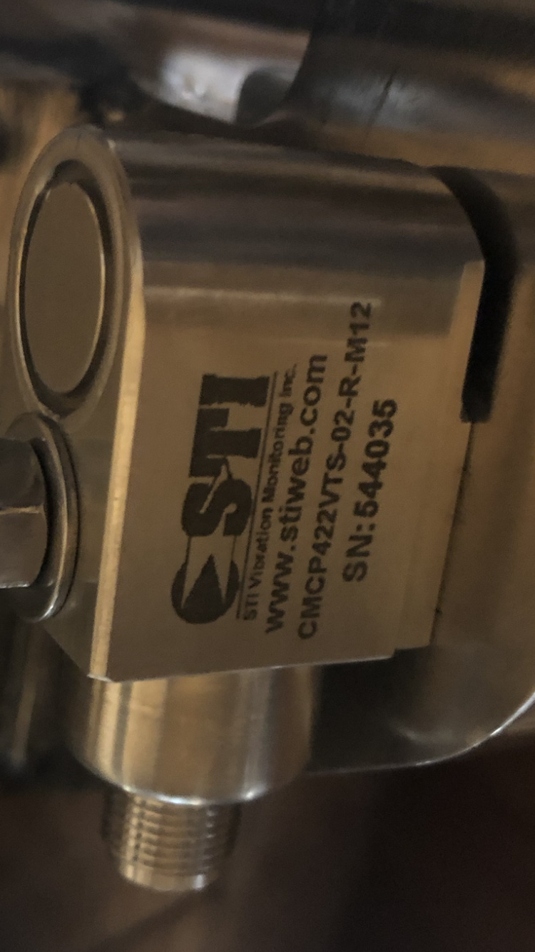
That handles the button problem. Next, you would need to add the sensor to make it the same as hitting the button. This means using two safety relays, DPDT or DPST NO that are regularly powered by your vibration sensor. Using two separate sensors here is actually one of the few cases where it might turn your SIL-2 up to SIL-3 although working out channel monitoring (which will trip the system if feedback is lost) is a little tougher and might take auxiliary contacts on those relays. This is where the PLC option shines.
The issue though is that those relays need to “latch” otherwise you’re depending on the drive not starting back up which is silly. Doing the physical wiring to make a NC circuit latch isnt tough and a quick Google search would probably spit it out. I’ll probably work up a diagram this weekend because I think this a fairly simple schema that might make a lot of people’s fuges, Chinese or otherwise, a shitload safer.
The PLC option is basically draw the same thing in TIA portal and just plug everything in lol.
I feel like one of the forum vendors could sell a sweet little panel to plug and play this, I can work up the schema and BOM if there’s interest.
Edit: sorry for the book of a post lol