PID controller help

Then you’ve got to figure out an enclosure, and a heat sink for that SSR.

Here is Jack, my first rosin press (ok second). The enclosure was sourced from Home Despot.

The heat sink is an iMac bracket purchased for $5 at the recycling center. pretty sure the red (hdpe cutting board) came from St Vinnies, and the jack stand was a harbor freight special the boss had lying around. cut and drilled a scrap of Alu plate, and added PIDs/thermocouples/cartidge heaters for about $150.

The later pictures are actually a different build, The Cauldron of Doom, which was a commercial soup pot I installed a salvaged 2kw heating element in (up from 750w?)

90% sure those SSR were salvaged too.

The soup pot fit my 10” MK III collection vessel like a glove, and I was going to use the pairing as a ethanol recovery still, but something bigger presented itself…

It was named such because it looked terrifying with a CLS in an overclocked witches pot…

Edit: ran into this on Craigslist today:
image
this was the starting point…

5 Likes

I guess @CapitalismSucks420’s build doesn’t require an enclosure…

I was certainly impressed with @SkyHighLer’s box-less build documented here: Distillation controllers with both temperature and power control

2 Likes

I was considering that actually yes. I might after the initial setup. My first goal is to get this thing working and connected to heat pads which I need that power source for.

The control voltage is 4 to 32 VDC, and the switched voltage is 24 to 380 VAC.

3 Likes

agreed (per BOTH of the 1k work substitutes I posted).

although technically one puts the lower limit at 3 volts and the other admits that even 2.4V might get the job done.

I’m not the one that needs help here :wink:

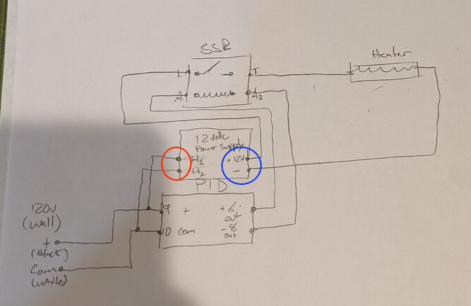
turns out your schematic, while not enough to get @CapitalismSucks420 to the goalposts, IS an implementation of

where @sids is trying to use an AC SSR to chop DC.

again

at this point all I got left in the bucket are forks…

2 Likes

Here is a schematic combining Sidvicious and mine:

You can use an extension cord to power up the wall wart DC power supply and just cut off the plug end to hook to the SCR.

3 Likes

I think it will work.

I will wait until my power supply comes in to make more adjustments.
Also, when I connect VAC end 1 thats the end I connect the extension cord wall plug to you mentioned?

I appreciate the help too:) this community is awesome!

2 Likes

On the cut end, the black wire in the extension cord attaches to terminal 2 on the SCR. The white wire attaches to terminal 9 on the PID or to the wire attached to terminal 9. The plug end of the extension cord goes to the wall wart power supply.

1 Like

Where does terminal 10 connect to on there?

“common”.
commonly referred to as “neutral”.

although if you follow it all the way to the distribution panel, you’ll find its actually connected to ground.

without it your wiggly (~) electrickery has nowhere to go, so it does nothing for you.

have you noticed that one blade on that 110V plug is wider than the other? Which blade you reckon is “hot” and which is “neutral”?

if you were dealing with DC, which way you plugged it in would matter (well…not for that heater, but a motor or actual electronics).

with AC it doesn’t so much.
except for where the switch is.

polarized plugs are there so the switch cuts off the juice to the whole device, rather than just the last little bit back to ground.

'cause some folks are really grounded…and we don’t want them getting hurt.

:rofl:

edit: you do know you can click on the images and get up close and personal with them right?

2 Likes

same color coding as before.

only now white and black stars indicate the hot and neutral coming from your wall

3 Likes

It is easier to understand the difference between common and earth ground looking at a DC system and using AC residential color codes.

The DC generator uses a magnet rotating in a wire coil to pump a stream of electrons in a circle, with the stream going out to the device in the black wire, passing through the device at the point of use, and returning via the white wire and to earth earth ground at the generator.

At the point of use, black is hot, white is not, and the green leg grounds the using device to earth ground at point of use.

Same idea with AC systems, except the electrons no longer flow in a circle, but reverse directions once a second, so just oscillate back and forth.

In older two wire systems the white common and ground were combined, but in modern systems with a third ground wire, the common is a floating ground back to the generator and isolated from local earth ground.

The green wire is still local earth ground and is intended to provide a more direct path to ground than the person using a device that shorts out so that the hot wire comes in contact with the devices conductive metal structure.

3 Likes

Good points!

For clarity regarding the white and black stars, I suggest reversing them in your picture. The 120 VAC Line in is currently the black wire with the white star and common is the white wire with the black star.

Another tidbit of information with regard to switches and SSR used inside electronic panels. It is traditional to switch the black wire on residential circuits, but in electronics they may place the SSR after the device, to switch its return to the generator after it has done its work, rather than before. That allows them to use smaller amperage SSR’s, and the hot wires are inside a cabinet where they aren’t available to touch.

I personally always use a suitable sized SSR and switch the hot.

I saw yes, terminal 10 connects to common and connects to terminal 1, so I just connect 10 and 1? Just want to make sure I don’t have to plug 10 and 1 into a wall or something

Got some more wire. Gonna connect 10 and 1

Got it connected

Time for black wire now. Connecting 2 on the VAC rn

No. Terminal 10 is the common connection for the PID, but it does not connect to Terminal 1.

Terminal 1 is the SCR connection to 120VAC Line.

The Common leg of your power supply is the other wire that attaches to Terminal 10 or the wire going to Terminal 10.

When you see a schematic showing wires crossing, if it humps over the wire, it is not connected. Where it is connected, there is a small circle blacked in at the connection.

2 Likes

Ok. Disconnecting it rn.

Where would the white wire on terminal 10 connect to?

Take an extension cord and cut it in two, using the wall plug end to power up the system and the outlet end to connect to your DC power supply. Strip the wires back far enough to make your connections, et al.

Connect both white wires to Terminal 10.

Connect the black wire from the wall plug end to Terminal 9. Connect another wire from Terminal 9 to Terminal 1 on the SSR.

Connect the black wire from the receptacle end to Terminal 2 on the SCR.

Wire the two green wires together along with a third wire attached to your system ground.

1 Like

Ok got a black wire connected to 9 and connected to 1.

Getting an extension cord to connect 9 to a wall

I hope this is right. For now at least…

If I plug it in what will happen?