It helps when you have been in equipment manufacturing for 87 years like us ![]()
Okay so I was speaking with @cyclopath and @Photon_noir about a proper control system for these centrifuges in accordance with their functional safety assessments and, well, life sometimes gets in the way. IEC 61508 and ISO 13849 are the standards that apply to this equipment and pretty clearly require substantial infrastructure to ensure safe operation in light of the likelihood of risk coupled with the catastrophic nature of the modes of failure involved.
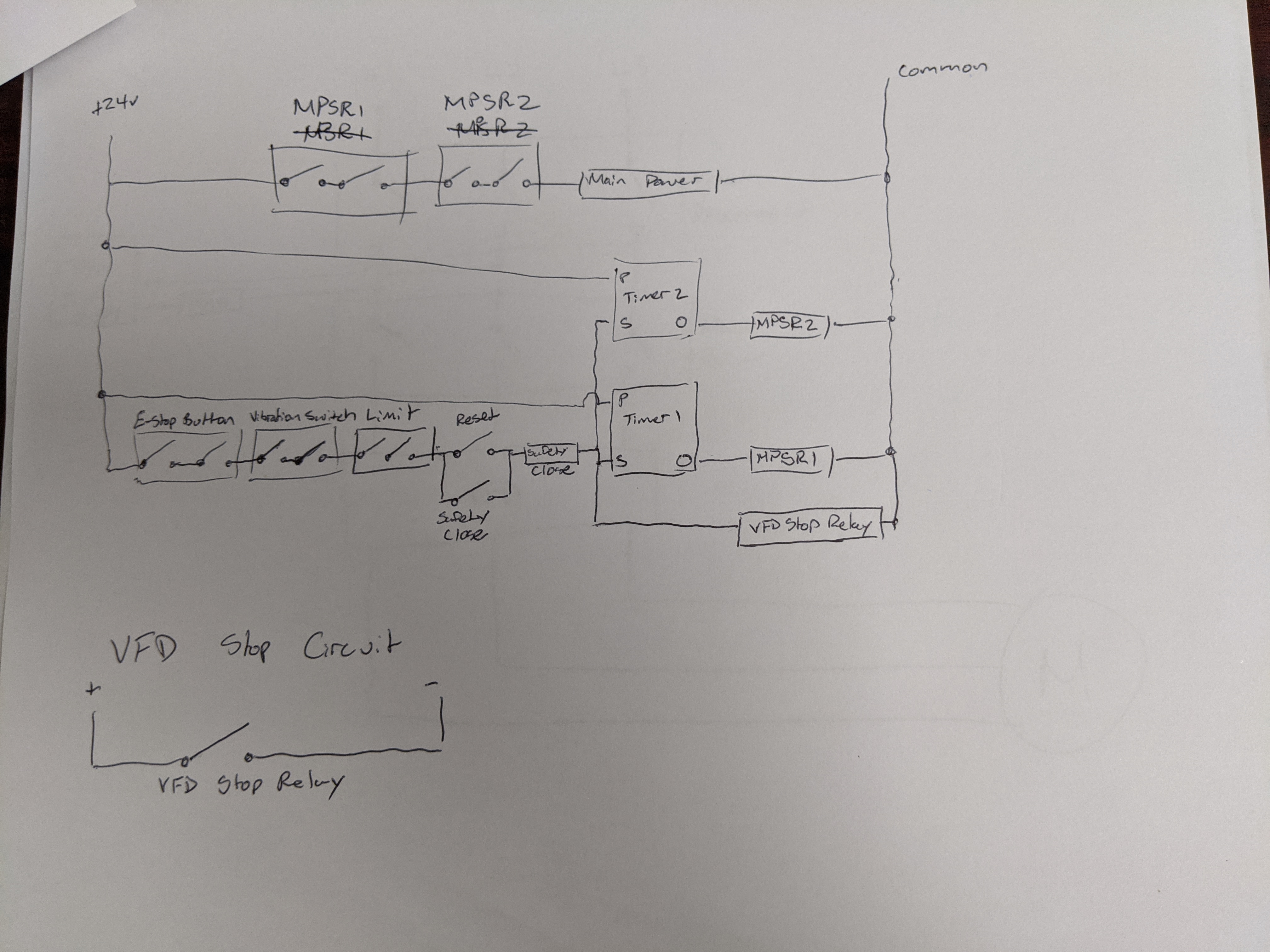
Unfortunately since this topic was started things got busy but I don’t like to waste time. I’ve attached a schematic for a basic e-stop control system that should be easily implemented to make pretty much any centrifuge able to safely stop. My goal is to provide a complete control system schema and BOM based on the Siemens platform which anyone with a Peony or equivalent fuge could install to make this systems safe and compliant with current codes and standards.
Since I’m afraid I won’t have a chance to do the step-by-step, I’m attaching my drawings (chicken scratch) because more info earlier is always better. For the import manufacturers, I hope you implement this system. For the domestic/European manufacturers, please review these standards and make sure you’re compliant, this industry will only accept being behind the times for so long.
I also think there’s a place here for someone (maybe one of our great forum vendors like @Killa12345 or @spdking) to make a plug-in retrofit package for these systems
TLDR; I’ma make a better diagram that’s easier to DIY soon but I don’t want to withhold the info.
9 Likes
soooo… that looks like the right way to perform this trick.
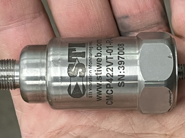
what say I moved the target, and the object of the game was to retrofit a vibration sensor to (say) this critter while finalizing/financing a real controller
seems like FRESH TAKEOUT MURPHY VS2EX VIBRATION SWITCH (640) | eBay could be slipped into the e-stop circuit, and provide some semblance of imbalance protection?
1 Like
I’ve got one of these vibration sensors from AD in a box on my desk right now. I’m going to be bolting it to a friend’s fuge next week.
I plan to toss various permutations of bag loadings from good to are you fuckin drunk? in it and see what it says.
Will report back if it is successful.
2 Likes
presumably you have full access to the programming on said fuge?
so that you can explain how it should respond to the 4-20mA signal?!?
That is certainly the plan for the production controller.
I have this one “in hand” for that trick, so I would absolutely appreciate an update on your “drunk operator detector”.
1 Like
Something like this controller might be workable as a programmable relay.
Put it inline in the e-stop circuit and wire the vibration sensor to it.
It’s a bit overkill for the requirements, but 5 minutes on google didn’t give me any great options for relays that will trigger based on a user-settable arbitrary 4-20mA setpoint.
1 Like
Ooh I like that. Thanks for the ![]()
1 Like
update: the FW Murphy explosion proof vibration switch has made a huge difference in our whirled. VS2™ Series | FW Murphy Production Controls
slipping in into the e-stop circuit in a normally closed configuration may not be the “right” way to add “tilt” to a Chinese fuge, but it works so well I want to try it on some of the bigger critters I get called in to work on.
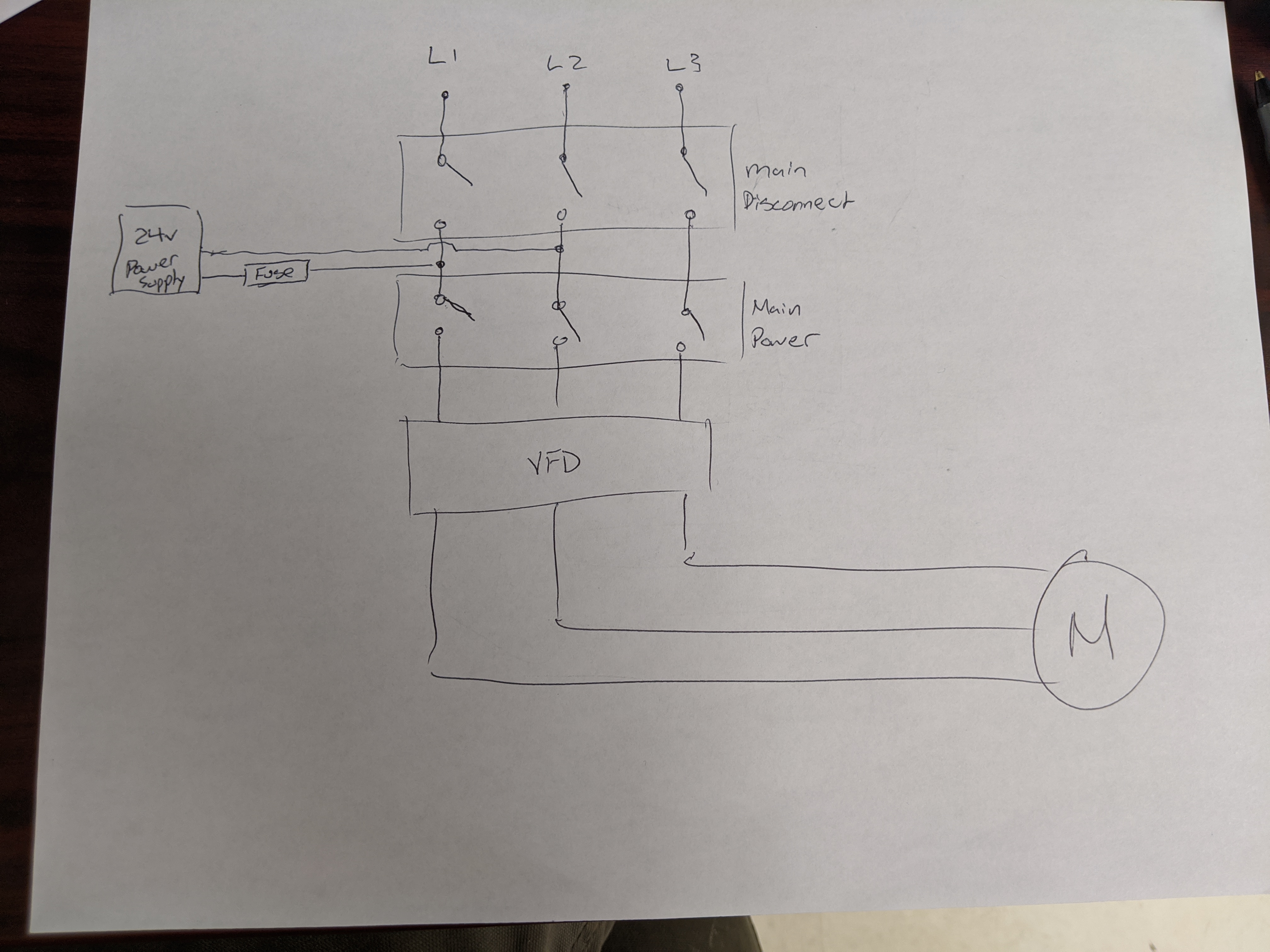
the part that has me confused currently is that the bigger fuges cut the power to the VFD when the e-stop (or tilt switch) is opened, but the little one cuts the power to the HMI and the VFD brakes the fuge to a stop. the components and wiring look identical. same brand of VFD and HMI touch screen. same general programming in vfd, and HMI.
I haven’t actually pulled the wiring diagrams or dug into the fine manual on the VFD again recently, but if someone (looking at you @SidViscous & @greenbuggy) has any clues on what I’m looking for, I would appreciate the assist, and so would the guys running these beasts.
1 Like
exactly.
we bolted the little one to the floor. first thing it did was offer to tear out the bolts and come after us. the murphy switch has been a wonderful addition. it would still be useful if it just cut the power, but a powered stop is definitely a bonus.
without a load in there I was able to get from 2500rpm to zero in 2 second…which is almost fast enough to implement a “please don 't climb in” switch. unfortunately, loaded, 20 seconds is a more reasonable request.
So I’m stuck… NOT adding a tilt switch to the bigger ones, where the wooks are left unsupervised and have to make their own decisions about what is and is not a life threatening unbalance, seems irresponsible. implementing a powered stop would be ideal. which requires figuring out how the “these look identical” controllers are configured to behave differently. almost certainly a useful learning experience. guess I ought dig in…
the goal is to build a complete controller for “my” fuge, or collaborate with @Lincoln20XX’s crew on that.
1 Like
My assumption from the stated description is that there is some small difference in the wiring.
Though I know we’ve discussed this one before and my brain tells me we may have ruled that one out?
Definitely getting into “stare at it and scratch your head for a day or two” territory on this one.
indeed.
I don’t think so. discussed how it seemed like a better implementation. My homework was probably to investigate further. …and they’re back in my life, so it’s time to look at it seriously.
trying to compare them from memory was not a win. the fuges are from different manufactures, but I’ve seen the same vfd & HMI from at least three vendors. similar but not identical…
If I’m lucky I’ve got wiring diagrams for both.
1 Like
Same general, or same exact?
You don’t say what brand/model VFD the two are fitted with, but some you can specify what kind of stop (coast to stop, DC inj braking, ramp to slow, etc) to happen under certain circumstances. If the little one has power cut to the HMI with an estop and the VFD is still powered but braking to a stop, it could be that its set to brake to stop when it sees a communication error with the VFD (assuming networked HMI/PLC/VFD). Could also be that it has an NC fast stop assigned pin, and when the HMI/PLC shuts off that circuit opens and the default VFD behavior is to brake to a stop
2 Likes