Mechanical Vapor Recompression for BHO: Recovery Without a Chiller

Recently I’ve been researching mechanical vapor recompression (MVR) which is an energy saving heat recovery process used in evaporation and distillation.

As with a lot of other processes in BHO extraction, this is actually an old technology that is widely known and implemented in various other industrial processes. It really just needed to be adapted and properly scaled down for our uses.

The basic idea involves recovering and recycling the latent heat of vaporization carried by the solvent vapor, rather than rejecting that heat during condensation.

A useful example I’ve used to envision this is to think about a pot of boiling water on the stovetop. If you put your hand above the liquid surface, you’ll notice the vapor is hot, at essentially the same temperature as the boiling liquid, about 100C for water at atmospheric pressure. Normally that heat is simply rejected to the atmosphere as the water boils, the same basic thing a recovery chiller or dry ice does on the recovery side in BHO while you continue adding fresh heat to the pot to maintain boiling.

So naturally you can ask, “why not just redirect that heat back into the pot?” The problem is temperature gradient. The vapor leaving the boiling liquid contains the large amount of latent heat used to generate it, but it’s at essentially the same temperature as the liquid, so there is no useful temperature difference to drive that heat back into it. This is where the compressor comes into play.

The compressor takes the vapor and raises its pressure. When you increase the vapor pressure, you also raise its boiling/condensation temperature, a.k.a. saturation temperature. The act of compression also raises the actual temperature of the vapor, so it will generally leave the compressor somewhat superheated relative to its new saturation temperature.

Imagine the steam from the boiling pot is at 100C and the liquid is also at 100C. You can’t effectively use one to heat the other. If you compress the steam to a pressure where it will condense at, say, 110C, you now have vapor on one side of the heat exchanger that can condense at 110C and boiling liquid on the other side at 100C. The compressed vapor first gives up any superheat, then begins to condense at roughly 110C, releasing its latent heat through the heat exchanger and back into the boiling liquid. That heat boils off another fraction of the liquid, which enters the compressor, gets recompressed, and the cycle continues.

The easiest way I’ve found to understand why this latent heat recycling is so powerful is to picture it frame by frame. Say an MVR setup has a 10 kW heater and, just for an easy example, is able to recover 90% of the heat used for evaporation. Of the first 10 kW put into generating vapor, roughly 9 kW gets transferred back into the liquid when that vapor condenses, while the heater continues adding another 10 kW. That recycled heat continues circulating and essentially snowballs until the heat being lost from the system balances the fresh energy being added.

Obviously that’s a simplified example that ignores compressor work, sensible heat, heat loses, etc. but it helped me understand that it’s not creating energy, it’s repeatedly recycling most of the latent heat instead of rejecting it every cycle.
5 Likes

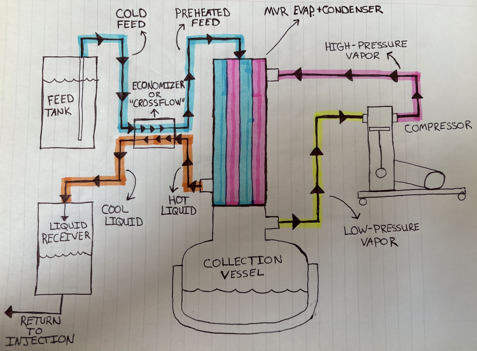
Here’s a simplified diagram I drew to show how this looks when applied to a hydrocarbon recovery system using a tube-in-shell heat exchanger configured as a falling film evaporator.

This is obviously just one implementation. MVR itself isn’t tied to a falling film tube-in-shell exchanger, a particular “crossflow” arrangement or any one specific hardware layout.

Working through the process flow, start with the yellow line as a familiar point for most of us: low-pressure vapor leaving the collection vessel and entering the compressor. The compressor raises its pressure and saturation temperature, and the resulting high-pressure vapor (pink) returns to the condensing side of the main exchanger. Because it now condenses at a higher temperature than the feed boiling on the other side, it releases its latent heat across the exchanger and boils off more solvent. That newly generated vapor heads back to the compressor and the cycle continues.

On the feed side (blue), cold feed first passes through an economizer or “crossflow,” where it is preheated before entering the falling film evaporator. Meanwhile the condensed liquid solvent leaving the main exchanger (orange) is still hot, so instead of sending it straight to the receiver, its remaining sensible heat is used to preheat that incoming feed. The recovered solvent leaves cooler and goes to the receiver while the feed enters the evaporator warmer.


So the main MVR exchanger is recovering latent heat, while the economizer is simply recovering additional sensible heat from the hot condensate. Preheating the feed with hot condensate is a long-established heat-recovery step in industrial evaporation systems.

The particular system that got me digging into all of this is the FluxWerx TurboVAP. What initially caught my attention was the recovery rate relative to the external heating/cooling requirement. FluxWerx has reported recovery in roughly the 10–12 lb/min range while only needing a few kW of trim heat once the system is operating and without relying on a conventional recovery chiller to handle the main condensation duty. Instead of dumping all of that latent heat into a chiller, the system is recycling it back into evaporation. It basically takes the old industrial MVR concept and scales it for BHO recovery.

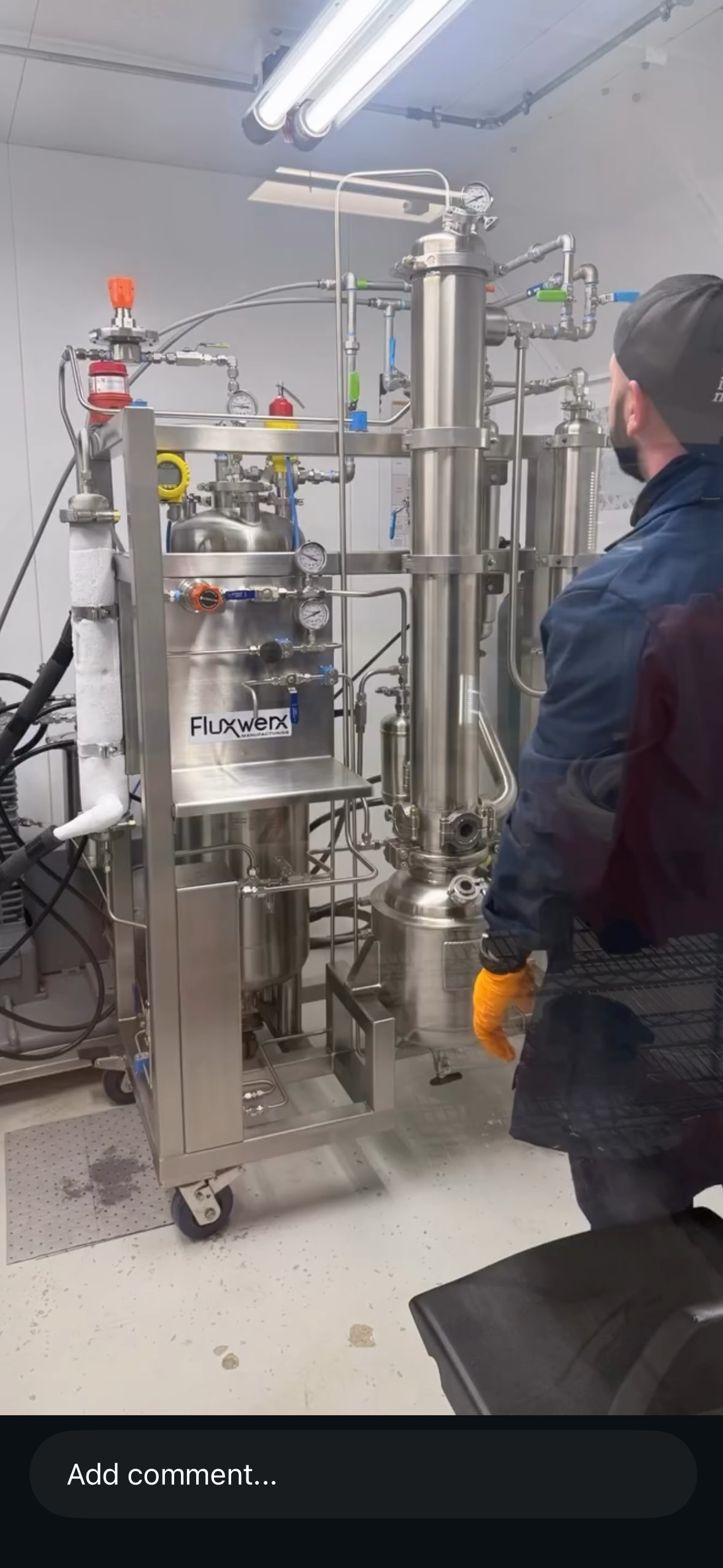
Here’s an actual FluxWerx TurboVAP installed in a booth. You can see the main vertical evaporator/condenser in the center-right, the feed vessel behind the skid, the compressor off to the left and the economizer/crossflow plate exchanger packaged into the lower-left portion of the skid.

My diagram obviously isn’t intended to show the exact TurboVAP plumbing or internals, just the general MVR architecture as I understand it.

That recovery rate makes a lot more sense once you look at the system as recycling a much larger latent-heat duty internally instead of supplying the entire evaporation load fresh on one side and then paying to reject that same heat with a recovery chiller on the other.

7 Likes

Great write up, my friend. MVR is great technology that’s been around for a very long time. If anybody is interested in an MVR evaporator, has questions, or wants to see one run, let us know. We do demos all the time!

2 Likes

Was digging through some old F4200 posts and stumbled back onto Indra/John Henry Davis and the Pure Extractor. I had forgotten how relevant his old patent actually is to this discussion.

His 2009 patent describes pulling hydrocarbon vapor from the extraction/collection vessels with a recovery compressor, then routing the compressed solvent vapor through the vessel jackets to supply the heat needed to keep solvent boiling. It specifically says the jackets allow the heat lost during solvent recovery to be recycled and that the solvent can leave the jackets as liquid.

That’s pretty damn close to the basic thermodynamic idea we’re talking about here with MVR: raise the vapor pressure and therefore its saturation/condensation temperature with a compressor and reuse that latent heat to boil more solvent on the low-pressure side.

Apparently this wasn’t forgotten on 4200 either. In 2020 there was a whole thread about using compressor outlet gas to heat the collection vessel and someone actually sketched essentially the same idea. CollectiveObjective immediately pointed out that Indra’s Pure Extractor was already designed to take hot vapor from the compressor outlet and pass it through the collection/recovery vessel jacket as a heating source.

The funny part is that a year later Illuminated was talking about having “re-invented the air conditioner” with their thermal-control system. Lmao, apparently cannabis has been rediscovering vapor recompression for a while.

Indra’s implementation apparently wasn’t especially fast, as early operators reported long recovery times and a second recovery pump was eventually added to improve throughput. This goes to show that the thermodynamic idea can be sound while the compressor sizing, heat-transfer area and supplemental heat input determine whether the thing actually performs.

4 Likes